Okay, I had a chance to look at a G80-0801.
First, to make sure that the numbering is consistent. I believe that in the close-up photo on Google Drive linked to above, it shows how S1 is numbered, with 1 at the top-left then 2 beside it. I therefore read the pinout as follows.
- S1:2 - DE-9:1 - green
- S1:3 - DE-9:6 - white
- S1:5 - DE-9:7 - brown
- S1:6 - DE-9:2 - yellow
I will use those numbers below.
- pin 6 is indeed +5V
- pin 2 is the always connected ground
- pin 5 is connected to ground if the switch is depressed, which is why it may have appeared to be ground
- pin 3 is the data line
Here is the back of the PCB:
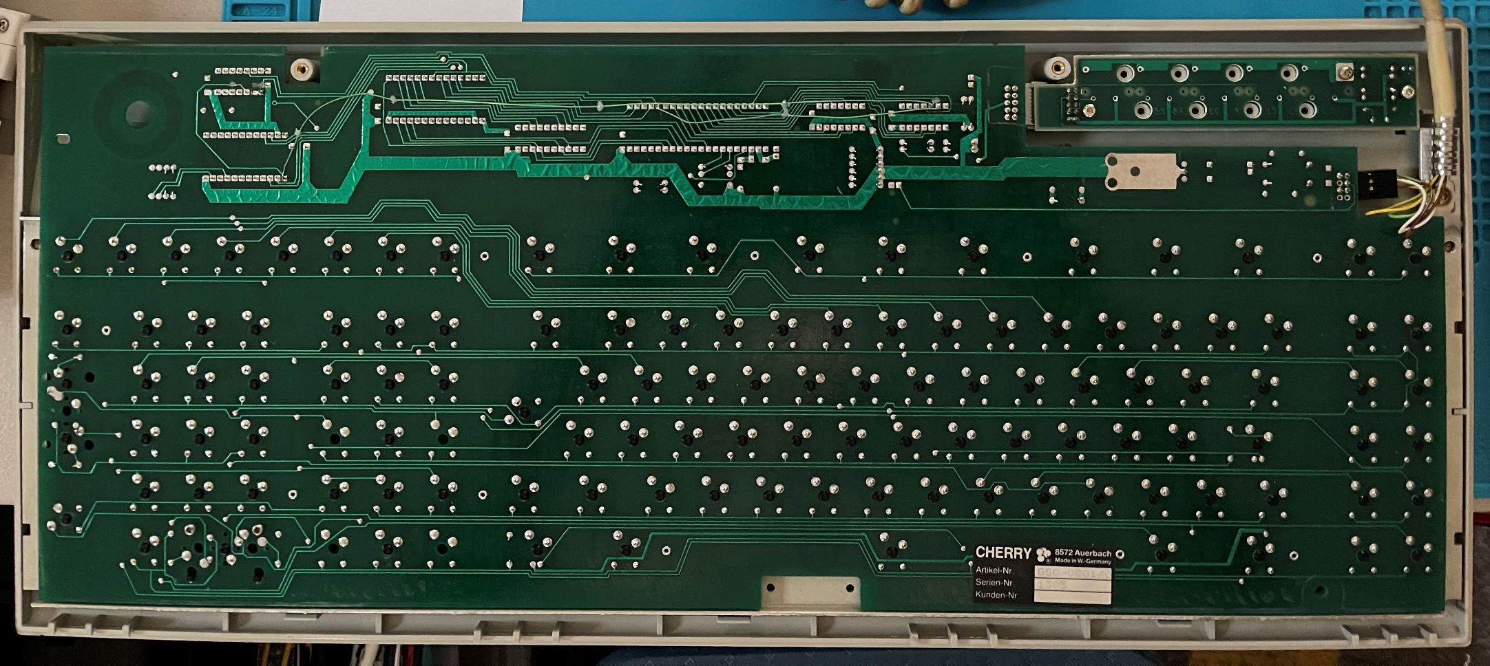
- G80-0801-bottom.jpg (481.46 KiB) Viewed 4623 times
Focusing first on the power daughter-card in the upper-right, the button connects pairs of pins horizontally. This powers the LED in the corner and also grounds pin 5.
The data line is unidirectional. It only goes to pin 10 of U2, an inverter. It can be seen here snaking over down and to the left of that chip. And in one of the other photos going underneath it on the other side.
Pin 11 of U2 is connected to pin 38 of U4, the 8039. This is P27, the high bit of port 2. So, the data output is that inverted (and cleaned up).
As for what that data is, it's TTL level serial, idle high, 2400 baud. And it's ASCII, more or less. Specifically, it's some German codepage where ä is {, ö |, ü }, ẞ ~.
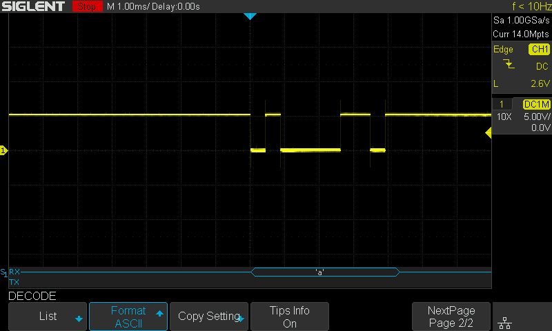
- G80-0801-a.png (23.7 KiB) Viewed 4623 times
All the cool function keys are just "characters" with the eighth bit set, as are the ALT forms of the letters.
There is no key release transitions or shift states exposed. CTRL is ASCII control.
A proper USB converter will need a new controller.