Page 1 of 1
Would these Teensy++ 2.0 pins work?
Posted: 22 Aug 2019, 17:10
by abrahamstechnology
I'm working on a custom PCB driven by a Teensy++ 2.0, can someone tell me if the pins I'm using in my schematic would work?
Rows and columns are labeled plus 4 LEDs (forgot to add resistors, will add later)

- GatewayKBMC.PNG (25.59 KiB) Viewed 5528 times
Re: Would these Teensy++ 2.0 pins work?
Posted: 22 Aug 2019, 17:19
by Muirium
Ah, good, you already know to beware the LED on pin 6 / D6. I’ve always been told to avoid that one when hooking up a matrix. Or else you’d need to whack the LED itself.
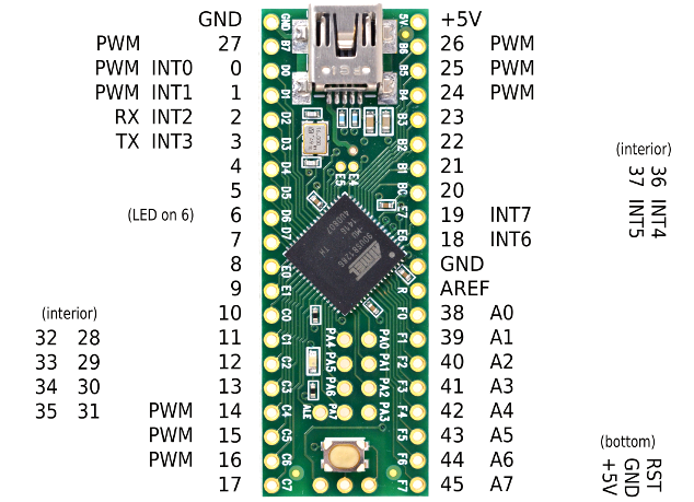 https://www.pjrc.com/teensy/pinout.html
I’d use their pin numbering, though. Quite confusing already!
Re: Would these Teensy++ 2.0 pins work?
Posted: 22 Aug 2019, 17:42
by abrahamstechnology
Muirium wrote: 22 Aug 2019, 17:19
Ah, good, you already know to beware the LED on pin 6 / D6. I’ve always been told to avoid that one when hooking up a matrix. Or else you’d need to whack the LED itself.
https://www.pjrc.com/teensy/pinout.html
I’d use their pin numbering, though. Quite confusing already!
Thanks. Can I use those "int" pins?
Re: Would these Teensy++ 2.0 pins work?
Posted: 22 Aug 2019, 17:48
by snacksthecat
Yes, "int" just means that those pins can be used for interrupts.
Re: Would these Teensy++ 2.0 pins work?
Posted: 22 Aug 2019, 18:02
by 4sStylZ
Basically if I am not wrong on a Teensy you can use all the pin for basic use (like boolean input / output 5V) except VCC / GND / D6 and maybe RST.
Re: Would these Teensy++ 2.0 pins work?
Posted: 22 Aug 2019, 18:18
by Muirium
RST is reset: it’s hooked up in parallel with the Teensy’s loader button. (You hook it to ground to trigger software update mode, right?) So it’s definitely on the no touch list.
It is a handy pin, though. Means you can put a reset button on your converter box for taking new firmware (I mean to do this to mine). Indeed, I wish they broke out the 4 usb pins too. That would save so much bother when running cables to a port.
Honestly, I’d love a community designed Teensy++ successor which has USB pin breakout.
Re: Would these Teensy++ 2.0 pins work?
Posted: 22 Aug 2019, 18:23
by Findecanor
I would consult the datasheet for the AT90USB1286 microcontroller that is in the Teensy++ 2.0.
Any digital pin on an AVR should work for rows and columns. Many I/O pins on AVR microcontrollers have multiple functions, and the those marked PWM, INT, Ax etc. are also digital pins.
For LEDs, you'd want to use a port/pins that are recommended in the datasheet for "driving"/"current source" and which has
PWM output for limiting the LEDs brightness. It is not an error to "direct drive" a keyboard LED at full brightness, but you might find that they could be too bright.
On most AVR microcontrollers, the best pins are typically pins B4 to B7, numbered 23 to 27 on the Teensy++ 2.0.
Do also read up on LEDs in the documentation of the firmware you intend to use.
I see only one type of direct error: LEDs are light-emitting
diodes so they work only connected one way. All but your Num Lock LED are in the wrong direction!
BTW. I would not use a sleep-LED, myself. Not only do I personally hate sleep LEDs, USB devices are not supposed to draw more than absolutely necessary in Suspend mode.
Re: Would these Teensy++ 2.0 pins work?
Posted: 22 Aug 2019, 18:31
by Findecanor
Muirium wrote: 22 Aug 2019, 18:18
Indeed, I wish they broke out the 4 usb pins too. That would save so much bother when running cables to a port.
Honestly, I’d love a community designed Teensy++ successor which has USB pin breakout.
The ARM Cortex-M - based Teensies have the USB D+/D- exposed as SMD pads.
This includes the long Teensy 3.5 and 3.6.
BTW. The Pro Micro-pinout compatible
Elite-C and
QMK Proton C expose D+/D- as pins (but you can't make a footprint that fits both

)
Re: Would these Teensy++ 2.0 pins work?
Posted: 22 Aug 2019, 19:59
by abrahamstechnology
Findecanor wrote: 22 Aug 2019, 18:23
I would consult the datasheet for the AT90USB1286 microcontroller that is in the Teensy++ 2.0.
Any digital pin on an AVR should work for rows and columns. Many I/O pins on AVR microcontrollers have multiple functions, and the those marked PWM, INT, Ax etc. are also digital pins.
For LEDs, you'd want to use a port/pins that are recommended in the datasheet for "driving"/"current source" and which has
PWM output for limiting the LEDs brightness. It is not an error to "direct drive" a keyboard LED at full brightness, but you might find that they could be too bright.
On most AVR microcontrollers, the best pins are typically pins B4 to B7, numbered 23 to 27 on the Teensy++ 2.0.
Do also read up on LEDs in the documentation of the firmware you intend to use.
I see only one type of direct error: LEDs are light-emitting
diodes so they work only connected one way. All but your Num Lock LED are in the wrong direction!
BTW. I would not use a sleep-LED, myself. Not only do I personally hate sleep LEDs, USB devices are not supposed to draw more than absolutely necessary in Suspend mode.
Thanks for the help and suggestions. The reason I'm adding extra LEDS is because the original case has windows for them (will add the message LED too, any way I can get this working in QMK?)

- vintage-gateway-104-key-ps-wired_1_810c1c291e9a0771d9f2afbecf846bfc.jpg (183.82 KiB) Viewed 5433 times
Re: Would these Teensy++ 2.0 pins work?
Posted: 22 Aug 2019, 20:09
by swampangel
abrahamstechnology wrote: 22 Aug 2019, 19:59
Thanks for the help and suggestions. The reason I'm adding extra LEDS is because the original case has windows for them (will add the message LED too, any way I can get this working in QMK?)
Assuming for the message led, you need to send a notification from the host to the kb,
https://www.reddit.com/r/olkb/comments/ ... er_on_qmk/ might get you started. I've been looking at this in the hopes of showing notifications with a WS2812 led strip, but I'm not very far along.
Re: Would these Teensy++ 2.0 pins work?
Posted: 22 Aug 2019, 20:13
by abrahamstechnology
Thanks again and here is my updated schematic (using a bicolor LED for the message light, the original had two individual LEDs near the window (also my matrix schematic is already done))

- GUPDATED.PNG (35.86 KiB) Viewed 5422 times
Re: Would these Teensy++ 2.0 pins work?
Posted: 23 Aug 2019, 02:09
by Mazian
For QMK, the LED pins are used as current sinks. That is, the Teensy is connected to the ground side of the LED-resistor pair, and a constant +5V from the power supply is connected on the other side. Opposite LED polarity from the schematic above.
Re: Would these Teensy++ 2.0 pins work?
Posted: 23 Aug 2019, 08:58
by Muirium
Findecanor wrote: 22 Aug 2019, 18:31
BTW. The Pro Micro-pinout compatible
Elite-C and
QMK Proton C expose D+/D- as pins (but you can't make a footprint that fits both
)
Thanks, Fin. The Proton looks promising, albeit out of stock on all four links. I don’t mind footprint issues as I’m no PCB designer. The projects I have in mind are much more hands on.