Olympia ES 100 keyboard conversion for PC use
Posted: 09 Feb 2018, 00:32
Olympia ES 100 keyboard conversion for PC use
Hi there. I've decided to document my venture into converting Olympia electric typewriter board for PC use. Specificaly the one with Marquardt Butterfly switches, since I think these are really underrated, not talked about much. And very undeservedly so, they're excelent switches.
1.1 Format
This is mainly build log not a guide. I'm far to newbie at this stuff to make an actual guide. But I will try to make it as universal and easy to "follow" and share as much info as posssible, for people actually interested in doing similar thing.
1.2 Boards
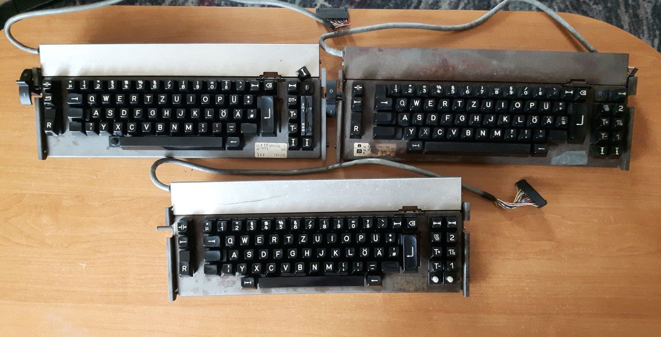
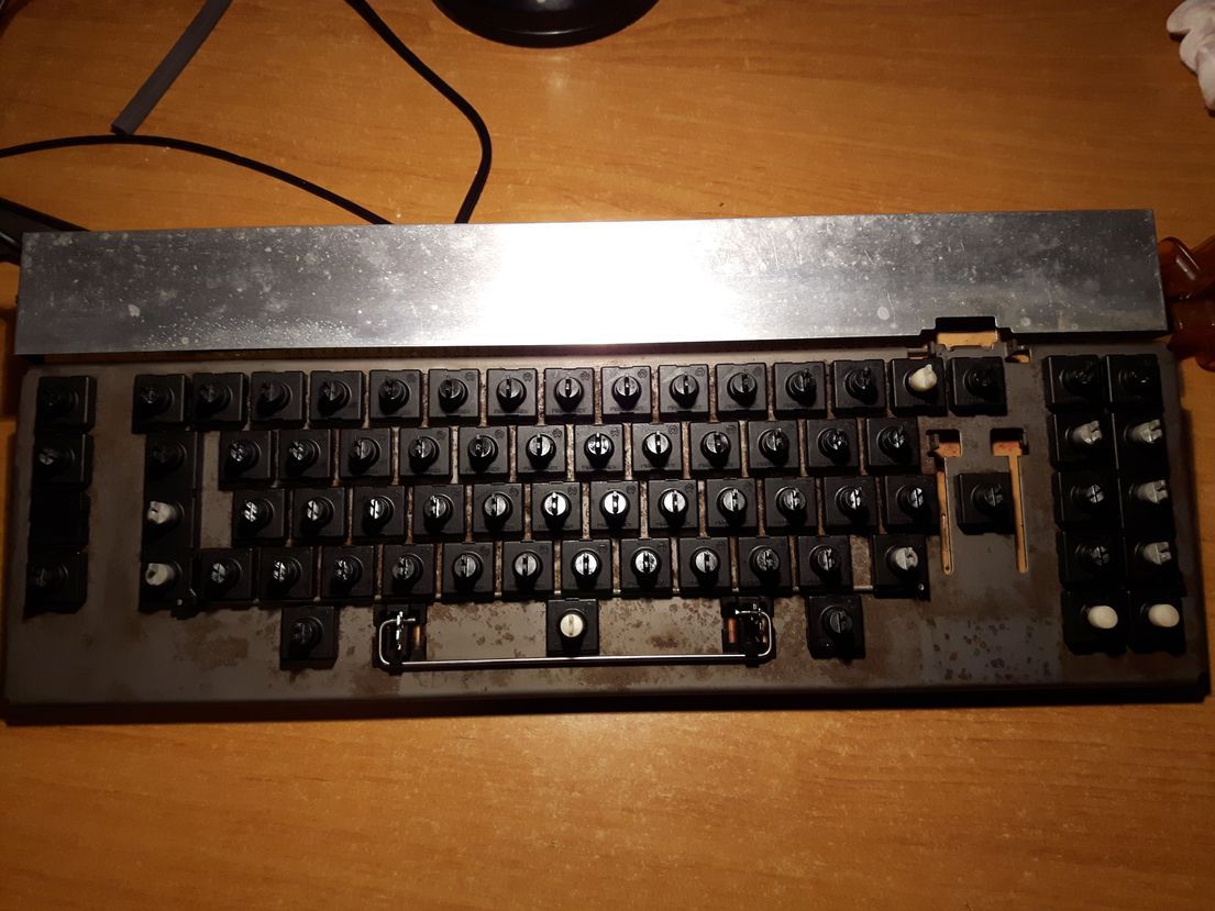
Currently I own 3 boards with these switches. One ES 101 and two variants of ES 100. They're all in different shape as can be seen from the picture. For the project I'm going to use ES 100 (bottom one) as main board, and ES 101 (top left) as a donnor for parts.
1.2.1 Known models that have butterfly switches
If you're searching for a board like this, the easiest way to spot one is the little orbit logo. Olympia Electric Standard line of typewrites made in early to mid 80s. Model numbers: ES 100, ES 101, ES 105 and probably ES 110 (not confirmed yet).
1.2.2 Maintenance tips
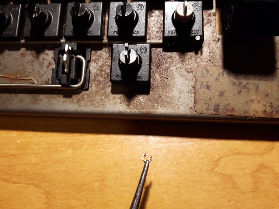
1. The easiest way to pull the caps off is prying them from bottom up with tweezers, needle-nose pliers... what have you. Since the mount is angled, I found this method reliable easy and safe. Of course you can use keypuller instead but be careful not to pull the caps straight up, because it can snap the slider mount off. They're not really robust when mishandled. It's a ~36 year old hardware...
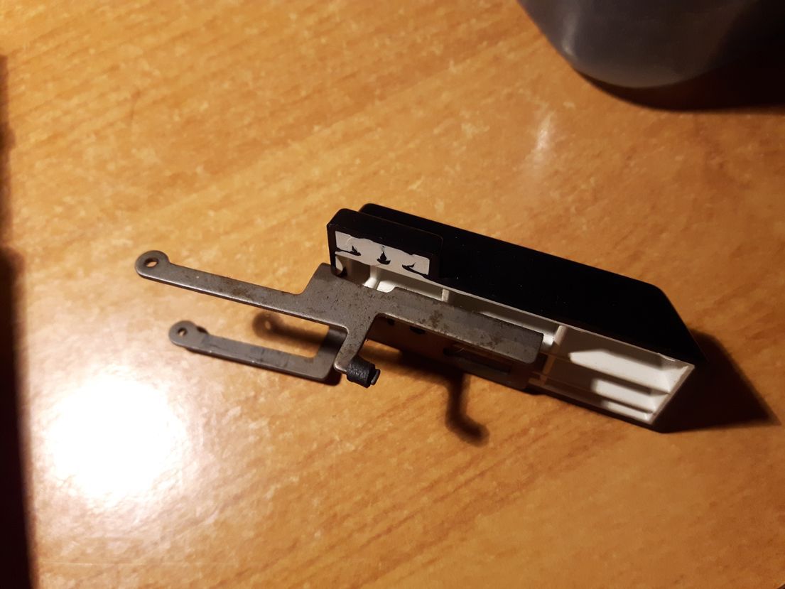
2. Enter key is heavily stabilized. In order to pull it off, firstly pull those little round metal thingies from the rod. Then remove the rod and the entire keycap will come of.
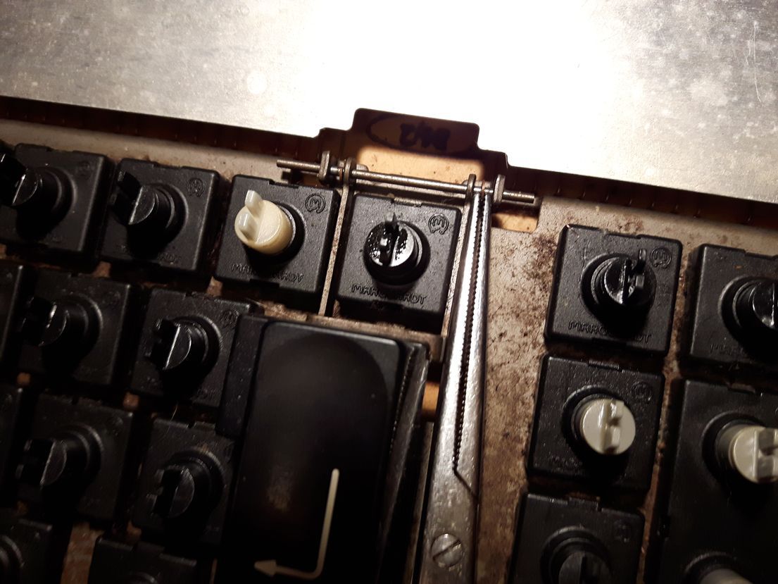
3. Dissasembling the switches for cleaning is really easy and can be done without desoldering the switch. Reasembling can be a little finicky, but once you get the hang of it, it's piece of cake.
1.3 Goals
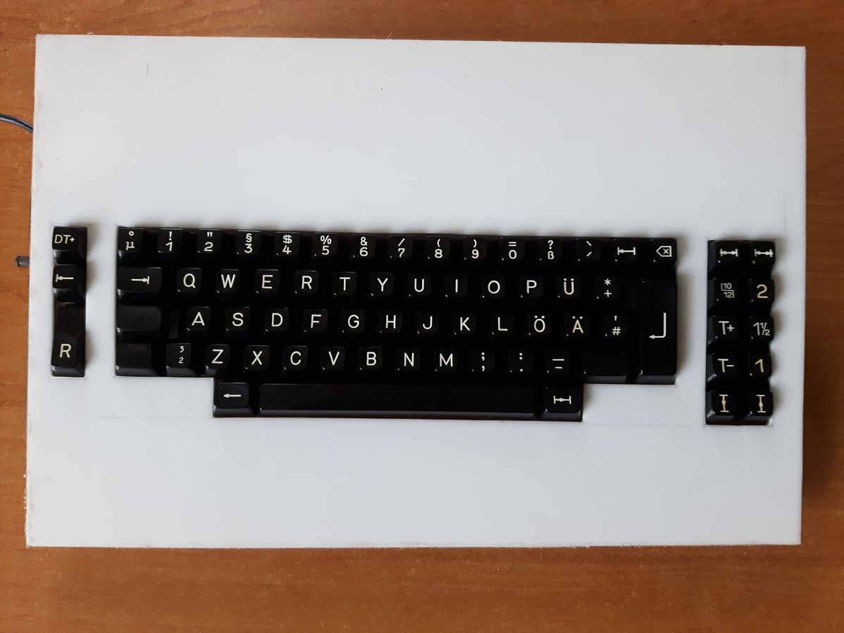
1.3.1 Vintage look
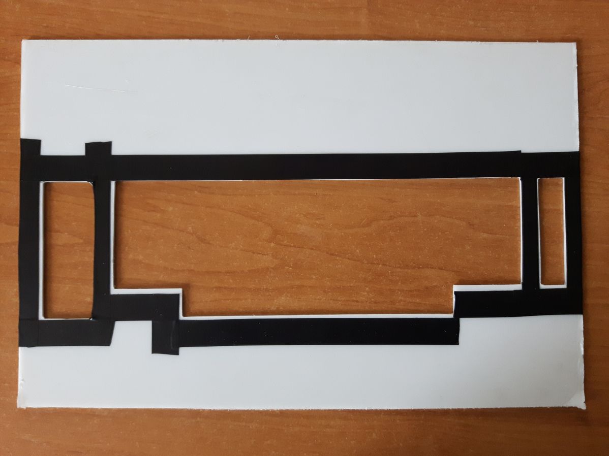
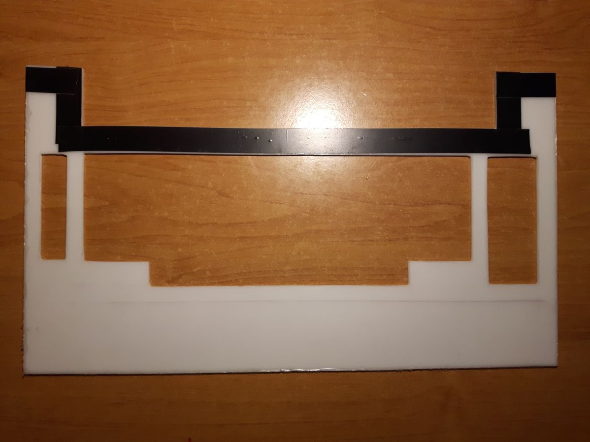
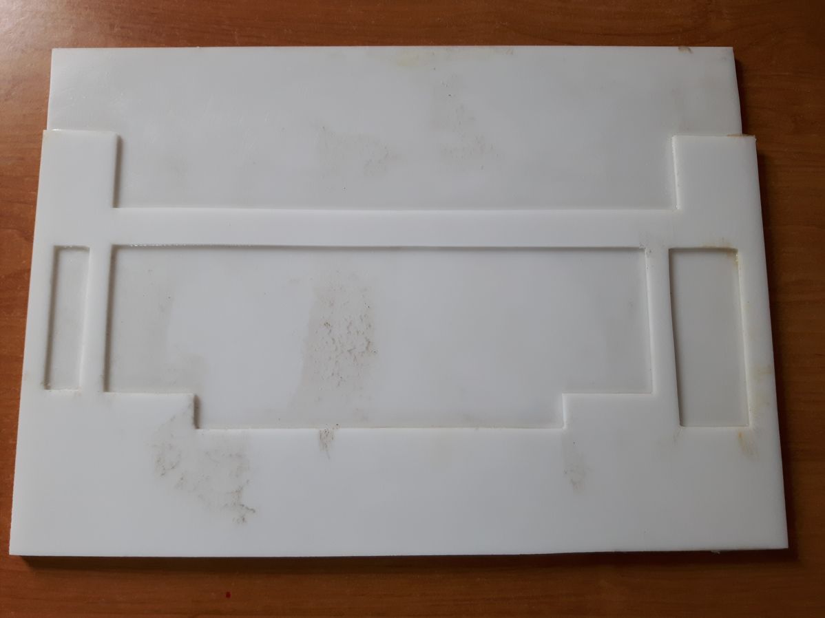
Most people making boards these days go for "modern" look. Which means small form factor, "naked" keys etc. I don't like it, it makes them look samey, and without character in my opinion. So the goal here is to make the opposite. We're going for the vintage look. Lots of presence, lots of "wasted" empty space and so on. Had many ideas (some very bizaare tbh) how the board supposed to look, but as it's my first project, so I need to constraim myself a little here. Not only because not realy sure what can be realistically pulled of with my skill set or lack thereof, but also because the choice of materials I'm going to use. Specificaly kydex sheets, that are not available bigger than in A3 format (40x30 cm). Which complicate things a little. Lets say it's a test run for future projects...
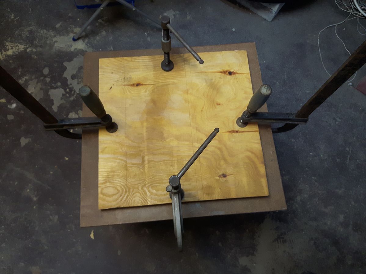
1.3.2 Made mostly from what's in the basement
Aside from parts that absolutely need to be bought, like connectors atmega boards and kydex. I will try to use stuff that's lying in my basement. Find it satysfying to repurpose old useless things lying around into something new. Like piece of wood from old closet, steel plate God knows where from or even old electronic devices. The obvious downside be, lots of try and error in the process and no pretty design set in stone from the start. The finished board may look way different
than what's in my head now.
Connecting to the PC
The process should be pretty straight forward, since keyboards from olympia have pretty modular design. No controller on board no wierd old protocols to deal with. Just a simple PCB with switchplate, mounted keys in one tidy package.
2.1 Keyboard matrix
2.1.1 Bottom of the PCB
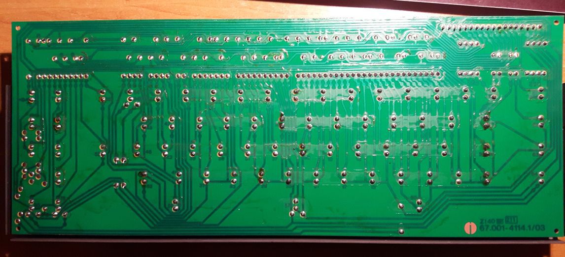
In the top right corner there's our pinout. Numbered (left to right) 1 to 18. All swtiches are numbered too, except the 3 button module on the left. So...
PCB --> reffers to switch number printed on the PCB
PIN 1 --> will be columns of our matrix (first leg of a given switch)
PIN 2 --> will be rows (second leg of a given switch)
As you probably noticed 4 keys on this board are double action. That's why they have 4 legs instead of 2. Vertcial contacts --> primary action of the swtich. Horizontal contacts --> secondary action of the
swtich.
Unnumbered 3 switch module will be used for layers. So let's call it layer2, layer3 respectively. Layer1 is default so we ignore it.
2.1.2 Let's find out what actual keys corespond to PCB numbers
Might as well check the pinout while we're at it...
2.1.3 Finished matrix in more readable form
CAPSLOCK, lSHIFT and rSHIFT - same pins same key. All secondary action ones are connected to same pins too, together with big R key. Cariage return is big thing in typewriter word it seems  PIN 14 is unused, so there is an option to add more switches, or leds for example. 10/12 key is a latching switch.
68 keys in total, which makes the board fit the 60% size category I guess...
2.2 Layout
Since we know how everything is conneted internally, it's time to think about the layout. But I'm to lazy to do a fancy picture. So brief description...
3 way lathing module on the right side will be the layers (1 - default , 2 - function, 3 - not used atm).
10/12 lathing switch on the right side is currently unused, but there's something planned for it.
Top row on the right side will be left and right. Bottom will be up and down. Those are double action so hard press will trigger CTRL+Up and CTRL+Down. Might be usefull to assign something to it in I3. Same with space and backspace. Hard press will trigger CTRL+space, CTRL+backspace.
T+ and T- are pageup and pagedown buttons.
ESC top left corner, Win key below it (never going to use it but what the hell) and the lCTRL = "big R". That's the first column.
Capslock and shift are on the same pins so we're gonna use the lShift key globally.
First layer is just a function layer.
Top row with numbers becomes F1-F12, WSAD and HJKL - arrow keys etc.
The rest is pretty much standard.
2.3 The controller
2.3.1 Test run
To avoid the unexpected surprises, it's good practice to do a test run before soldering the controller in. I've picked spacebar as a test button, which on the matrix is PIN 15 and PIN 8. Manualy connected first wire (simple loop) to PD2 pin on Pro Micro. And the second one to GND.
Flashed the Pro Micro with TMK keyboard\onekey with two small edits in onekey.c In matrix_init and matrix_scan functions changed default pin from PB0 to PD2. Connected keyboard to pc, pressed spacebar few times
and saw "a" popping up in terminal. Cool everything works as expected.
2.3.2 Soldering
This part is self explanatory. Rows to the left, columns to the right for simplicity. Wired mine like this.
Cannot count so the PIN5 landed at the bottom...
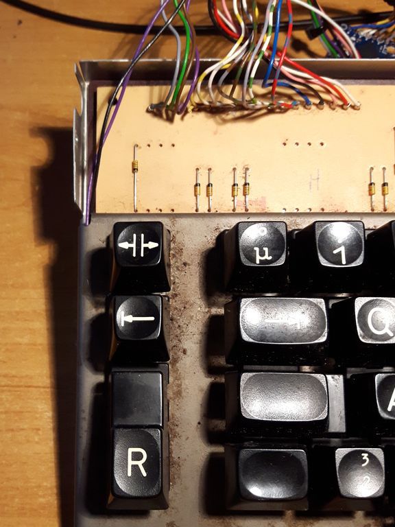
2.3.3 Reset switch
I've decided to add the reset switch, at the place that can be easily accessed. It's good thing to have, for fine tuning firmware in the future. Dummy switch under cariage return <CR> ("big R") seems like a perfect spot. With board fully assembled I can acces it simply by puling out the cap and dummy switch cover.
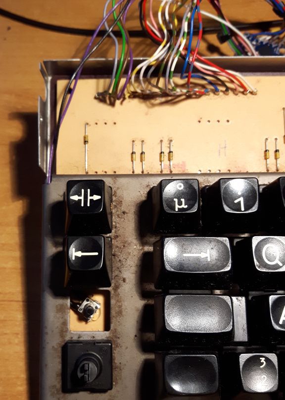
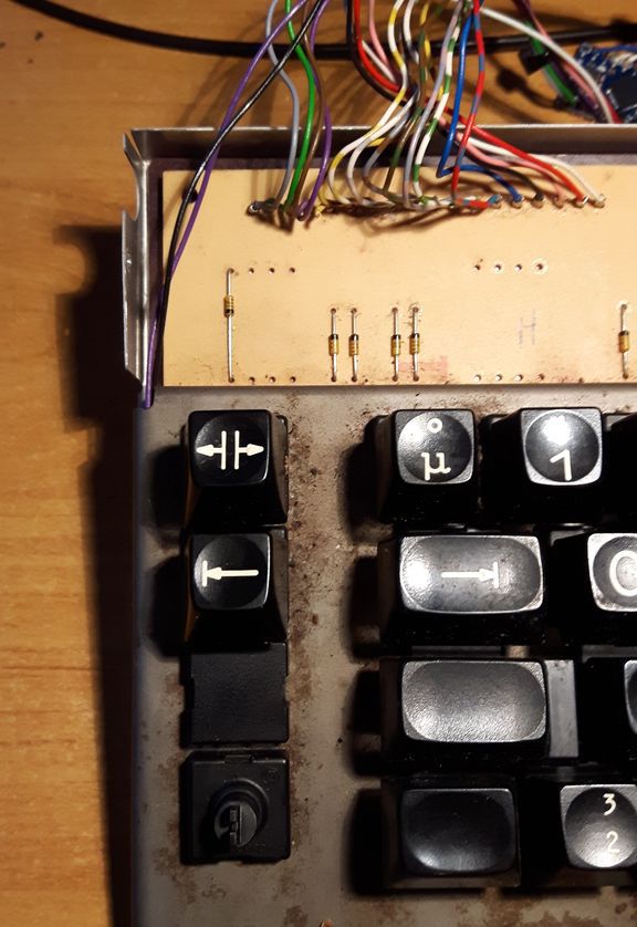
Bit of hot glue and the switch is in place. Two wires go to RST and GND pin on the Pro Micro board.
2.3.4 Arrrgh
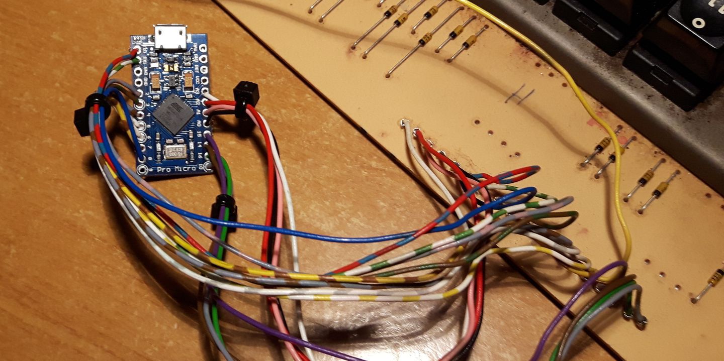
Usually don't like to do this, but the Pro Micro board has no mounting holes. And I'm to stupid to think of any clever way to attach this thing. So hot glue it is... bleh... seriously use the hot glue as last resort...
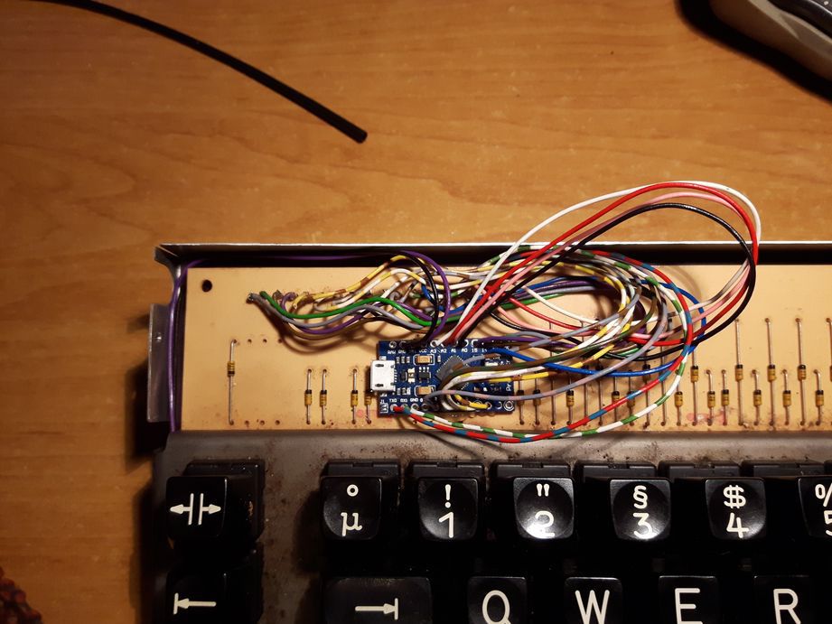
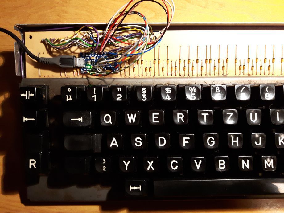
Yeah I left out waaay to much wire lenght wise. Cable management ain't pretty. But it works, and that's the most important thing right? Also worth noting, standard micro USB fits, but the connection is very tight. The plug sits on a diode. So swapped the cable for one with slimmer plug instead. Not in the picture but you get the idea.
2.4 Firmware
Used gh60 as base, and edited it accordingly.
2.4.1 matrix.c
2.4.2 keymap_common.h
2.4.3 keymap_olympia_E100.c
2.5 Cleanup
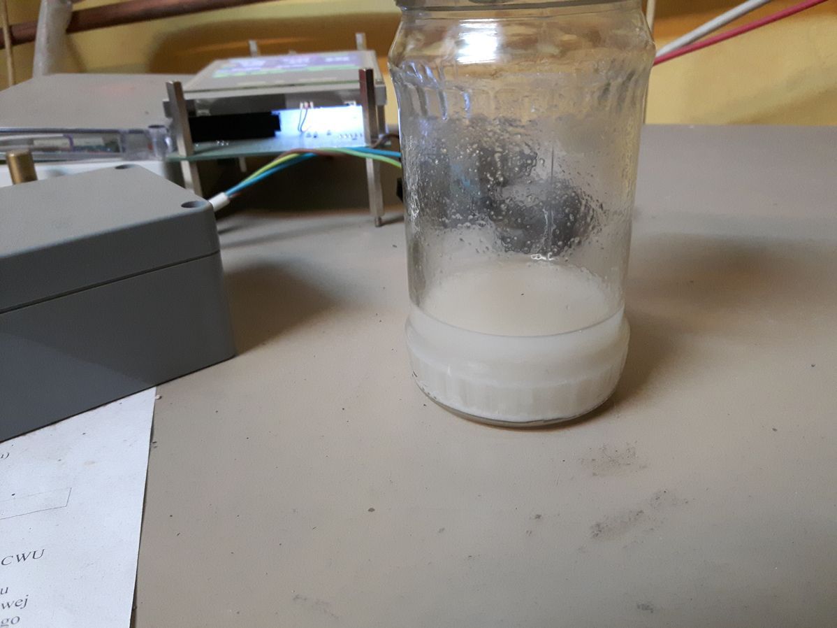
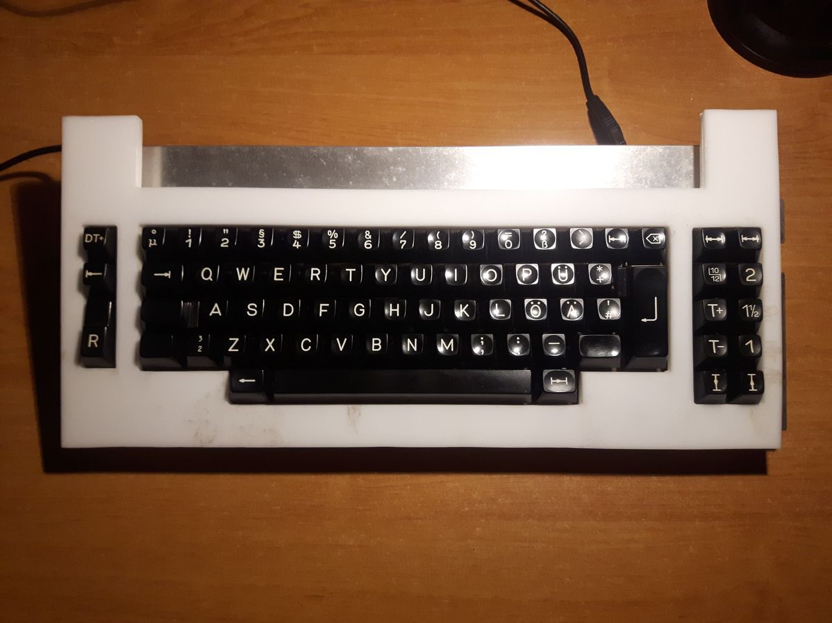
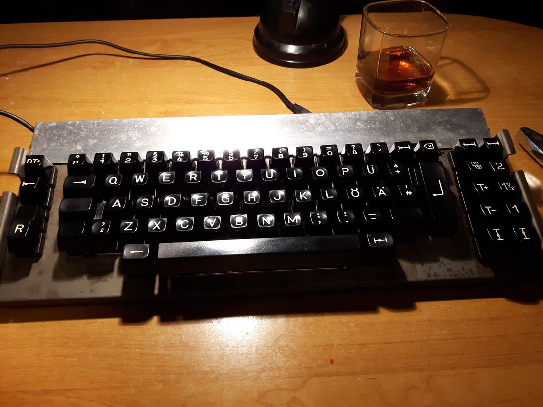
Well it's finally time to clean this thing up. Was able to ged rid of most of the gunk with soap, and some alcohol (not that one in the glass ). The switchplate is quite rusty though. Sanding and painting is on the TODO list. This wil have to wait till spring though. [board_cleaned] [assembled_after_cleaning] Really don't know what those white spots at the top cover are. Scrubbing does not get rid of it. This part needs a paint job too...
TBC
Hi there. I've decided to document my venture into converting Olympia electric typewriter board for PC use. Specificaly the one with Marquardt Butterfly switches, since I think these are really underrated, not talked about much. And very undeservedly so, they're excelent switches.
1.1 Format
This is mainly build log not a guide. I'm far to newbie at this stuff to make an actual guide. But I will try to make it as universal and easy to "follow" and share as much info as posssible, for people actually interested in doing similar thing.
1.2 Boards
Currently I own 3 boards with these switches. One ES 101 and two variants of ES 100. They're all in different shape as can be seen from the picture. For the project I'm going to use ES 100 (bottom one) as main board, and ES 101 (top left) as a donnor for parts.
1.2.1 Known models that have butterfly switches
If you're searching for a board like this, the easiest way to spot one is the little orbit logo. Olympia Electric Standard line of typewrites made in early to mid 80s. Model numbers: ES 100, ES 101, ES 105 and probably ES 110 (not confirmed yet).
1.2.2 Maintenance tips
1. The easiest way to pull the caps off is prying them from bottom up with tweezers, needle-nose pliers... what have you. Since the mount is angled, I found this method reliable easy and safe. Of course you can use keypuller instead but be careful not to pull the caps straight up, because it can snap the slider mount off. They're not really robust when mishandled. It's a ~36 year old hardware...
2. Enter key is heavily stabilized. In order to pull it off, firstly pull those little round metal thingies from the rod. Then remove the rod and the entire keycap will come of.
3. Dissasembling the switches for cleaning is really easy and can be done without desoldering the switch. Reasembling can be a little finicky, but once you get the hang of it, it's piece of cake.
1.3 Goals
1.3.1 Vintage look
Most people making boards these days go for "modern" look. Which means small form factor, "naked" keys etc. I don't like it, it makes them look samey, and without character in my opinion. So the goal here is to make the opposite. We're going for the vintage look. Lots of presence, lots of "wasted" empty space and so on. Had many ideas (some very bizaare tbh) how the board supposed to look, but as it's my first project, so I need to constraim myself a little here. Not only because not realy sure what can be realistically pulled of with my skill set or lack thereof, but also because the choice of materials I'm going to use. Specificaly kydex sheets, that are not available bigger than in A3 format (40x30 cm). Which complicate things a little. Lets say it's a test run for future projects...
1.3.2 Made mostly from what's in the basement
Aside from parts that absolutely need to be bought, like connectors atmega boards and kydex. I will try to use stuff that's lying in my basement. Find it satysfying to repurpose old useless things lying around into something new. Like piece of wood from old closet, steel plate God knows where from or even old electronic devices. The obvious downside be, lots of try and error in the process and no pretty design set in stone from the start. The finished board may look way different
than what's in my head now.
Connecting to the PC
The process should be pretty straight forward, since keyboards from olympia have pretty modular design. No controller on board no wierd old protocols to deal with. Just a simple PCB with switchplate, mounted keys in one tidy package.
2.1 Keyboard matrix
2.1.1 Bottom of the PCB
In the top right corner there's our pinout. Numbered (left to right) 1 to 18. All swtiches are numbered too, except the 3 button module on the left. So...
PCB --> reffers to switch number printed on the PCB
PIN 1 --> will be columns of our matrix (first leg of a given switch)
PIN 2 --> will be rows (second leg of a given switch)
As you probably noticed 4 keys on this board are double action. That's why they have 4 legs instead of 2. Vertcial contacts --> primary action of the swtich. Horizontal contacts --> secondary action of the
swtich.
Unnumbered 3 switch module will be used for layers. So let's call it layer2, layer3 respectively. Layer1 is default so we ignore it.
2.1.2 Let's find out what actual keys corespond to PCB numbers
Might as well check the pinout while we're at it...
Code: Select all
  ---------------------------------------------------------------------------------------
   PCB    01  02  03  04  05  06  07  08  09  10  11  12  13  14  15  16  17  18  19  20
  ---------------------------------------------------------------------------------------
   Key     1   Q   A   2   Y   W   S   3   X   E   D   4   C   R   F   5   V   T   G   6
   PIN 1  17  17  17  18  18  18  18  18  18  18  16  16  16  16  16  16  16  16  15  15
   PIN 2   6  10   7  13   9  12  11   6   7  10   9  12  11   6  10   7  13   8  12   6
  ---------------------------------------------------------------------------------------

  ---------------------------------------------------------------------------------------
   PCB    21  22  23  24  25  26  27  28  29  30  31  32  33  34  35  36  37  38  39  40
  ---------------------------------------------------------------------------------------
   KEY     B   Z   H   7   N   U   J   8   M   I   K   9   ,   O   L   0   .   P   Ö   ß
   PIN 1  15  15  15  15   4   4   4   4   4   4   4   4   3   3   3   3   3   3   3   3
   PIN 2  10   7  13   9  12   8  11   6  10   7  13   9   8  11   6   7  13   9  12  10
  ---------------------------------------------------------------------------------------

  ------------------------------------------------------------------------------------------
   PCB    41  42  43  44  45  46  47  48   49    50      51      52     53       54      55
  ------------------------------------------------------------------------------------------
   KEY     _   Ü   Ä   ´   +   #  32   µ  TAB  CAPS  lSHIFT  rSHIFT  ENTER  wBCKSPC  BCKSPC
   PIN 1   2   2   2   2   2   2  17  17   17    17      17      17      1        2       1
   PIN 2   6  10  13   9  12   8  11   8   12     5       5       5     10       11       7
  ------------------------------------------------------------------------------------------

  ---------------------------------------------------------------------------------------------------------
   PCB      56     57    58   61    62     63     64    71     72  73  74    75     76  80  layer2  layer3
  ---------------------------------------------------------------------------------------------------------
   KEY    lALT  SPACE  rALT  ESC  :<--  DUMMY  big R  LEFT  10/12  T+  T-  DOWN  RIGHT  UP   1 1/2       2
   PIN 1    18     15     2   17    17     18     15     1      1   1   1     1      1   1       2       3
   PIN 2     8      8     7    9    13      5     11    13      5  12   6    11      9   8       5       5
  ---------------------------------------------------------------------------------------------------------
Code: Select all
  ----------------------------------------------------------
   PIN  01      02       03      04  15     16  17    18
    05  10/12   layer2   layer3                 CAPS  DUMMY
    06  T-      _        L       8   6      R   1     3
    07  BCKSPC  rALT     0       I   Z      5   A     X
    08  UP      #        ,       U   SPACE  T   µ     lALT
    09  RIGHT   ´        P       9   7      D   ESC   Y
    10  ENTER   Ü        ß       M   B      F   Q     E
    11  DOWN    wBCKSPC  O       J   big R  C   32    S
    12  T+      +        Ö       N   G      4   TAB   W
    13  LEFT    Ä        .       K   H      V   :<--  2
  ----------------------------------------------------------
68 keys in total, which makes the board fit the 60% size category I guess...
2.2 Layout
Since we know how everything is conneted internally, it's time to think about the layout. But I'm to lazy to do a fancy picture. So brief description...
3 way lathing module on the right side will be the layers (1 - default , 2 - function, 3 - not used atm).
10/12 lathing switch on the right side is currently unused, but there's something planned for it.
Top row on the right side will be left and right. Bottom will be up and down. Those are double action so hard press will trigger CTRL+Up and CTRL+Down. Might be usefull to assign something to it in I3. Same with space and backspace. Hard press will trigger CTRL+space, CTRL+backspace.
T+ and T- are pageup and pagedown buttons.
ESC top left corner, Win key below it (never going to use it but what the hell) and the lCTRL = "big R". That's the first column.
Capslock and shift are on the same pins so we're gonna use the lShift key globally.
First layer is just a function layer.
Top row with numbers becomes F1-F12, WSAD and HJKL - arrow keys etc.
The rest is pretty much standard.
2.3 The controller
2.3.1 Test run
To avoid the unexpected surprises, it's good practice to do a test run before soldering the controller in. I've picked spacebar as a test button, which on the matrix is PIN 15 and PIN 8. Manualy connected first wire (simple loop) to PD2 pin on Pro Micro. And the second one to GND.
Flashed the Pro Micro with TMK keyboard\onekey with two small edits in onekey.c In matrix_init and matrix_scan functions changed default pin from PB0 to PD2. Connected keyboard to pc, pressed spacebar few times
and saw "a" popping up in terminal. Cool everything works as expected.
2.3.2 Soldering
This part is self explanatory. Rows to the left, columns to the right for simplicity. Wired mine like this.
Code: Select all
  ---------------------
   PIN  Pro Micro  PIN
     6  PD3   RAW
     7  PD2   GND
        GND   RST
        GND   VCC
     8  PD1   PF4    1
     9  PD0   PF5    2
    10  PD4   PF6    3
    11  PC6   PF7    4
    12  PD7   PB1   15
    13  PE6   PB3   16
     5  PB4   PB2   17
        PB5   PB6   18
  ---------------------
2.3.3 Reset switch
I've decided to add the reset switch, at the place that can be easily accessed. It's good thing to have, for fine tuning firmware in the future. Dummy switch under cariage return <CR> ("big R") seems like a perfect spot. With board fully assembled I can acces it simply by puling out the cap and dummy switch cover.
Bit of hot glue and the switch is in place. Two wires go to RST and GND pin on the Pro Micro board.
2.3.4 Arrrgh
Usually don't like to do this, but the Pro Micro board has no mounting holes. And I'm to stupid to think of any clever way to attach this thing. So hot glue it is... bleh... seriously use the hot glue as last resort...
Yeah I left out waaay to much wire lenght wise. Cable management ain't pretty. But it works, and that's the most important thing right? Also worth noting, standard micro USB fits, but the connection is very tight. The plug sits on a diode. So swapped the cable for one with slimmer plug instead. Not in the picture but you get the idea.
2.4 Firmware
Used gh60 as base, and edited it accordingly.
2.4.1 matrix.c
Code: Select all
/*
Copyright 2012 Jun Wako <wakojun@gmail.com>

This program is free software: you can redistribute it and/or modify
it under the terms of the GNU General Public License as published by
the Free Software Foundation, either version 2 of the License, or
(at your option) any later version.

This program is distributed in the hope that it will be useful,
but WITHOUT ANY WARRANTY; without even the implied warranty of
MERCHANTABILITY or FITNESS FOR A PARTICULAR PURPOSE.  See the
GNU General Public License for more details.

You should have received a copy of the GNU General Public License
along with this program.  If not, see <http://www.gnu.org/licenses/>.
*/

/*
 * scan matrix
 */
#include <stdint.h>
#include <stdbool.h>
#include <avr/io.h>
#include <util/delay.h>
#include "print.h"
#include "debug.h"
#include "util.h"
#include "matrix.h"


#ifndef DEBOUNCE
#   define DEBOUNCE	5
#endif
static uint8_t debouncing = DEBOUNCE;

/* matrix state(1:on, 0:off) */
static matrix_row_t matrix[MATRIX_ROWS];
static matrix_row_t matrix_debouncing[MATRIX_ROWS];

static matrix_row_t read_cols(void);
static void init_cols(void);
static void unselect_rows(void);
static void select_row(uint8_t row);


void matrix_init(void)
{
    // initialize row and col
    unselect_rows();
    init_cols();

    // initialize matrix state: all keys off
    for (uint8_t i=0; i < MATRIX_ROWS; i++) {
        matrix[i] = 0;
        matrix_debouncing[i] = 0;
    }
}

uint8_t matrix_scan(void)
{
    for (uint8_t i = 0; i < MATRIX_ROWS; i++) {
        select_row(i);
        _delay_us(30);  // without this wait read unstable value.
        matrix_row_t cols = read_cols();
        if (matrix_debouncing[i] != cols) {
            matrix_debouncing[i] = cols;
            if (debouncing) {
                debug("bounce!: "); debug_hex(debouncing); debug("\n");
            }
            debouncing = DEBOUNCE;
        }
        unselect_rows();
    }

    if (debouncing) {
        if (--debouncing) {
            _delay_ms(1);
        } else {
            for (uint8_t i = 0; i < MATRIX_ROWS; i++) {
                matrix[i] = matrix_debouncing[i];
            }
        }
    }

    return 1;
}

inline
matrix_row_t matrix_get_row(uint8_t row)
{
    return matrix[row];
}

/* Column pin configuration
 * col: 0   1   2   3   4   5   6   7
 * pin: F4  F5  F6  F7  B1  B3  B2  B6
 */

static void  init_cols(void)
{
    // Input with pull-up(DDR:0, PORT:1)
    DDRF  &= ~(1<<7 | 1<<6 | 1<<5 | 1<<4);
    PORTF |=  (1<<7 | 1<<6 | 1<<5 | 1<<4);
    DDRB  &= ~(1<<6 | 1<<3 | 1<<2 | 1<<1);
    PORTB |=  (1<<6 | 1<<3 | 1<<2 | 1<<1);

}

static matrix_row_t read_cols(void)
{
    return (PINF&(1<<4) ? 0 : (1<<0)) |
           (PINF&(1<<5) ? 0 : (1<<1)) |
           (PINF&(1<<6) ? 0 : (1<<2)) |
           (PINF&(1<<7) ? 0 : (1<<3)) |
           (PINB&(1<<1) ? 0 : (1<<4)) |
           (PINB&(1<<3) ? 0 : (1<<5)) |
           (PINB&(1<<2) ? 0 : (1<<6)) |
           (PINB&(1<<6) ? 0 : (1<<7));
}

/* Row pin configuration
 * row: 0   1   2   3   4   5   6   7   8
 * pin: B4  D3  D2  D1  D0  D4  C6  D7  E6
 */


static void unselect_rows(void)
{
    // Hi-Z(DDR:0, PORT:0) to unselect
    DDRB  &= ~0b00010000;
    PORTB &= ~0b00010000;
    DDRD  &= ~0b10011111;
    PORTD &= ~0b10011111;
    DDRC  &= ~0b01000000;
    PORTC &= ~0b01000000;
    DDRE  &= ~0b01000000;
    PORTE &= ~0b01000000;

}

static void select_row(uint8_t row)
{
    // Output low(DDR:1, PORT:0) to select
    switch (row) {
        case 0:
            DDRB  |= (1<<4);
            PORTB &= ~(1<<4);
            break;
        case 1:
            DDRD  |= (1<<3);
            PORTD &= ~(1<<3);
            break;
        case 2:
            DDRD  |= (1<<2);
            PORTD &= ~(1<<2);
            break;
        case 3:
            DDRD  |= (1<<1);
            PORTD &= ~(1<<1);
            break;
        case 4:
            DDRD  |= (1<<0);
            PORTD &= ~(1<<0);
            break;
        case 5:
            DDRD  |= (1<<4);
            PORTD &= ~(1<<4);
            break;
        case 6:
            DDRC  |= (1<<6);
            PORTC &= ~(1<<6);
            break;
        case 7:
            DDRD  |= (1<<7);
            PORTD &= ~(1<<7);
            break;
        case 8:
            DDRE  |= (1<<6);
            PORTE &= ~(1<<6);
            break;


    }
}
Code: Select all
/*
Copyright 2012,2013 Jun Wako <wakojun@gmail.com>

This program is free software: you can redistribute it and/or modify
it under the terms of the GNU General Public License as published by
the Free Software Foundation, either version 2 of the License, or
(at your option) any later version.

This program is distributed in the hope that it will be useful,
but WITHOUT ANY WARRANTY; without even the implied warranty of
MERCHANTABILITY or FITNESS FOR A PARTICULAR PURPOSE.  See the
GNU General Public License for more details.

You should have received a copy of the GNU General Public License
along with this program.  If not, see <http://www.gnu.org/licenses/>.
*/
#ifndef KEYMAP_COMMON_H
#define KEYMAP_COMMON_H

#include <stdint.h>
#include <stdbool.h>
#include "keycode.h"
#include "action.h"
#include "action_macro.h"
#include "report.h"
#include "host.h"
#include "print.h"
#include "debug.h"
#include "keymap.h"


/* GH60 keymap definition macro
 * K2C, K31 and  K3C are extra keys for ISO
 */
#define KEYMAP( \
    K46,   K36, K16, K87, K17, K75, K25, K14, K44, K13, K43, K22, K52, K41, K61, K20,   K80, K40, \
    K86,   K76, K56, K77, K57, K15, K35, K24, K33, K23, K62, K42, K51, K71,             K00, K02, \
    K07,   K06, K26, K67, K45, K55, K74, K84, K63, K83, K12, K72, K81, K31, K50,        K70, K01, \
    K64,        K66, K47, K27, K65, K85, K54, K73, K53, K32, K82, K11,                  K10,      \
                     K37,                     K34,           K21,                       K60, K30  \
) { \
    { KC_##K00, KC_##K01, KC_##K02, KC_NO,    KC_NO,    KC_NO,    KC_##K06, KC_##K07 }, \
    { KC_##K10, KC_##K11, KC_##K12, KC_##K13, KC_##K14, KC_##K15, KC_##K16, KC_##K17 }, \
    { KC_##K20, KC_##K21, KC_##K22, KC_##K23, KC_##K24, KC_##K25, KC_##K26, KC_##K27 }, \
    { KC_##K30, KC_##K31, KC_##K32, KC_##K33, KC_##K34, KC_##K35, KC_##K36, KC_##K37 }, \
    { KC_##K40, KC_##K41, KC_##K42, KC_##K43, KC_##K44, KC_##K45, KC_##K46, KC_##K47 }, \
    { KC_##K50, KC_##K51, KC_##K52, KC_##K53, KC_##K54, KC_##K55, KC_##K56, KC_##K57 }, \
    { KC_##K60, KC_##K61, KC_##K62, KC_##K63, KC_##K64, KC_##K65, KC_##K66, KC_##K67 }, \
    { KC_##K70, KC_##K71, KC_##K72, KC_##K73, KC_##K74, KC_##K75, KC_##K76, KC_##K77 }, \
    { KC_##K80, KC_##K81, KC_##K82, KC_##K83, KC_##K84, KC_##K85, KC_##K86, KC_##K87 }  \
}


/* ANSI variant. No extra keys for ISO */
#define KEYMAP_ANSI( \
    K00, K01, K02, K03, K04, K05, K06, K07, K08, K09, K0A, K0B, K0C, K0D, \
    K10, K11, K12, K13, K14, K15, K16, K17, K18, K19, K1A, K1B, K1C, K1D, \
    K20, K21, K22, K23, K24, K25, K26, K27, K28, K29, K2A, K2B,      K2D, \
    K30, K32, K33, K34, K35, K36, K37, K38, K39, K3A, K3B,           K3D, \
    K40, K41, K42,           K45,                     K4A, K4B, K4C, K4D  \
) KEYMAP( \
    K00, K01, K02, K03, K04, K05, K06, K07, K08, K09, K0A, K0B, K0C, K0D, \
    K10, K11, K12, K13, K14, K15, K16, K17, K18, K19, K1A, K1B, K1C, K1D, \
    K20, K21, K22, K23, K24, K25, K26, K27, K28, K29, K2A, K2B, NO,  K2D, \
    K30, NO,  K32, K33, K34, K35, K36, K37, K38, K39, K3A, K3B, NO,  K3D, \
    K40, K41, K42,           K45,                NO,  K4A, K4B, K4C, K4D  \
)


#define KEYMAP_HHKB( \
    K00, K01, K02, K03, K04, K05, K06, K07, K08, K09, K0A, K0B, K0C, K0D, K49,\
    K10, K11, K12, K13, K14, K15, K16, K17, K18, K19, K1A, K1B, K1C, K1D, \
    K20, K21, K22, K23, K24, K25, K26, K27, K28, K29, K2A, K2B,      K2D, \
    K30, K32, K33, K34, K35, K36, K37, K38, K39, K3A, K3B,      K3D, K3C, \
    K40, K41, K42,           K45,                     K4A, K4B, K4C, K4D  \
) KEYMAP( \
    K00, K01, K02, K03, K04, K05, K06, K07, K08, K09, K0A, K0B, K0C, K0D, \
    K10, K11, K12, K13, K14, K15, K16, K17, K18, K19, K1A, K1B, K1C, K1D, \
    K20, K21, K22, K23, K24, K25, K26, K27, K28, K29, K2A, K2B, NO,  K2D, \
    K30, NO,  K32, K33, K34, K35, K36, K37, K38, K39, K3A, K3B, K3C, K3D, \
    K40, K41, K42,           K45,                K49, K4A, K4B, K4C, K4D  \
)

#endif
Code: Select all
#include "keymap_common.h"


const uint8_t PROGMEM keymaps[][MATRIX_ROWS][MATRIX_COLS] = {
    /* Keymap 0: default layer */
    KEYMAP(ESC,   GRV, 1, 2, 3, 4, 5, 6, 7, 8, 9, 0, MINS, EQL, BSPC,DELETE,  LEFT, RGHT, \
	   LGUI,  TAB, Q, W, E, R, T, Y, U, I, O, P, LBRC, RBRC,              NO,   NO,   \
	   FN1,   LSFT,A, S, D, F, G, H, J, K, L, SCLN, QUOT,BSLS, ENT,       PGUP, FN0,  \
	   LCTL,   BSLS,Z, X, C, V, B, N, M, COMM, DOT, SLSH,                 PGDN,      \
	               LALT,         SPC,              RALT,                  DOWN, UP),

    /* Keymap 1: FN layer */
    KEYMAP(ESC,   TRNS, F1,  F2,  F3,   F4,  F5,  F6,  F7,  F8,  F9,   F10, F11, F12, BSPC, DELETE,   LEFT, RGHT, \
	   LGUI,  TAB,  TRNS,UP,  TRNS, TRNS,END, HOME,PGDN,PGUP,END,  TRNS,TRNS,TRNS,                NO,   NO,   \
	   FN1,   LSFT, LEFT,DOWN,RIGHT,TRNS,TRNS,LEFT,DOWN,UP,  RIGHT,TRNS,TRNS,BSLS,  ENT,          PGUP, FN0,   \
	   LCTL,   TRNS,TRNS,TRNS,TRNS, TRNS,TRNS,TRNS,TRNS,TRNS,TRNS, TRNS,                          PGDN,      \
	               LALT,         SPC,              RALT,                                          DOWN, UP),

};

const action_t PROGMEM fn_actions[] = {
	   [0] = ACTION_LAYER_MOMENTARY(1),                  // FN0
};Well it's finally time to clean this thing up. Was able to ged rid of most of the gunk with soap, and some alcohol (not that one in the glass
TBC