- unspecified.jpg (470.9 KiB) Viewed 8057 times
Replacing the Controller in my logitech g610
-
NaTaKa
- Location: Deutschland
- Main keyboard: Logitech g610
- Main mouse: mx Anywhere 2
- Favorite switch: mx brown
- DT Pro Member: -
Hi y'all , I was wondering how hard it could be to replace / reprogram the Controller in my Logitech G610, it is a soldered Arm chip, Im not afraid of cutting traces, but I dont Know how to determite if a Tensy would Work, also i dond need "per key backlight" so the controller could go , a simple led driver chip vould be enought, I am also wondering if just buyng a new PCB and desoldering all my MX browns would be more economic ( Im in germany so shipping from the US would kill my budget)
-
Dilettant
- Location: Germany
- DT Pro Member: -
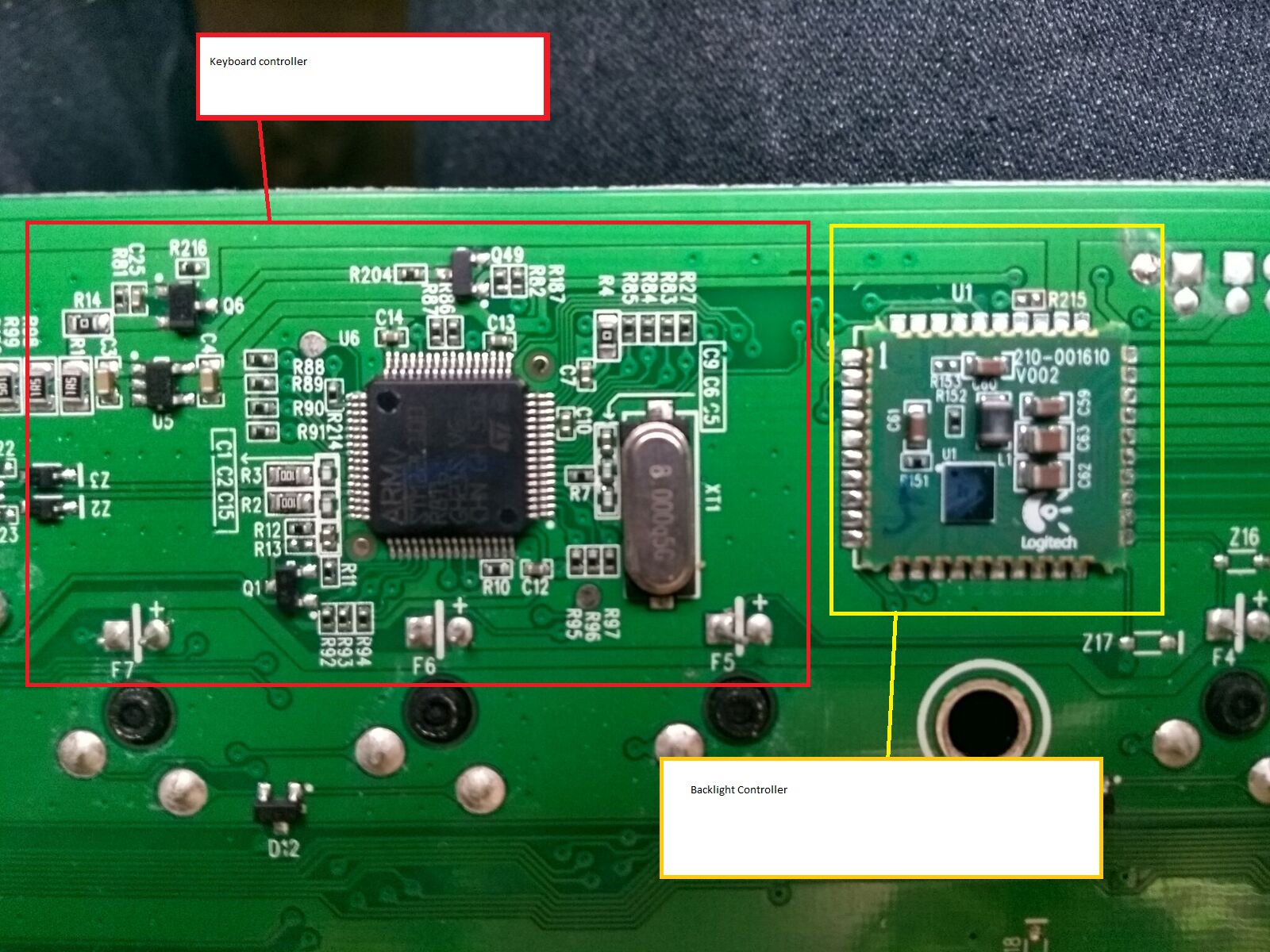
Hi NaTaKa! Though you didn't receive any feedback, were you successful with your project? I received a bricked G610 and also want to replace the controller with a Teensy. So far I determined how the matrix is organized (see attached image - hope I got everything right). Now I need to decide whether it's better to desolder the chip (and possibly the LED controller) or to cut traces.
I'm also not sure yet how to connect the rows to the teensy. The columns are simpler because they don't involve diodes and I can simply solder to a switch pin. I fear that for the columns, soldering a wire to the tiny connectors of the chip will be too delicate for my miserable soldering skills. But I also fear that soldering a wire to one SMD diode in each row might displace the diode and I might not be able to properly put it back again.
I'm also not sure yet how to connect the rows to the teensy. The columns are simpler because they don't involve diodes and I can simply solder to a switch pin. I fear that for the columns, soldering a wire to the tiny connectors of the chip will be too delicate for my miserable soldering skills. But I also fear that soldering a wire to one SMD diode in each row might displace the diode and I might not be able to properly put it back again.
- logitech_g610_matrix.png (51.76 KiB) Viewed 7152 times
Last edited by Dilettant on 02 Nov 2019, 11:03, edited 2 times in total.
-
Muirium

- µ
- Location: Edinburgh, Scotland
- Main keyboard: HHKB Type-S with Bluetooth by Hasu
- Main mouse: Apple Magic Mouse
- Favorite switch: Gotta Try 'Em All
- DT Pro Member: µ
As it happens, I was up to something similar recently. And it worked. The keyboard I was converting was an Access-IS matrix POS board (with the proprietary PS/2 programmable controller from hell). Damn thing was utterly useless until I popped in a Teensy. Works a treat now.
Fortunately, it had a modular design. I simply removed the original controller.
Then instead of hooking up a Teensy to the ribbon connector, I jumped it onto nice big easy solder joints on well chosen switches. Yes, switch pins for both rows and columns. How so? Well, keyboard matrices work like this:

The columns on that diagram are obvious. Just pick a conveniently located switch pin from each one of those lines.
The rows work the same way. But what about the diodes? I’m not trained in electronics, but I found I could ignore them. Just act as though they’re not present. The diodes are about blocking false signals (masking and ghosting). Real signals pass through them as designed. So don’t worry about them and go pick a convenient pin for each row, too. (If I’m wrong, feel free to correct me. Maybe this only works half the time, depending on diode orientation?)
Once you’re all soldered up, you configure your Teensy’s keyboard controller firmware: telling TMK or Soarer’s Controller (my pick, as I’m used to his tools) which pins are rows and which are columns. If no key presses show up, swap them around. I got the Access conversion right on the first attempt (all 96 switches present, correct, and NKRO!) which says something for this being fairly easy in practice.
Now! There is one difference with what you’re doing. You guys have an integrated controller you want to work around. I’ll be interested to see how you do that. I’ve several boards of my own with controllers right on the switch PCB that I’d like to replace, especially for Bluetooth conversion.
Fortunately, it had a modular design. I simply removed the original controller.
Then instead of hooking up a Teensy to the ribbon connector, I jumped it onto nice big easy solder joints on well chosen switches. Yes, switch pins for both rows and columns. How so? Well, keyboard matrices work like this:
The columns on that diagram are obvious. Just pick a conveniently located switch pin from each one of those lines.
The rows work the same way. But what about the diodes? I’m not trained in electronics, but I found I could ignore them. Just act as though they’re not present. The diodes are about blocking false signals (masking and ghosting). Real signals pass through them as designed. So don’t worry about them and go pick a convenient pin for each row, too. (If I’m wrong, feel free to correct me. Maybe this only works half the time, depending on diode orientation?)
Once you’re all soldered up, you configure your Teensy’s keyboard controller firmware: telling TMK or Soarer’s Controller (my pick, as I’m used to his tools) which pins are rows and which are columns. If no key presses show up, swap them around. I got the Access conversion right on the first attempt (all 96 switches present, correct, and NKRO!) which says something for this being fairly easy in practice.
Now! There is one difference with what you’re doing. You guys have an integrated controller you want to work around. I’ll be interested to see how you do that. I’ve several boards of my own with controllers right on the switch PCB that I’d like to replace, especially for Bluetooth conversion.
-
Dilettant
- Location: Germany
- DT Pro Member: -
I would love to play with such a grid layout!Muirium wrote: As it happens, I was up to something similar recently. And it worked. The keyboard I was converting was an Access-IS matrix POS board (with the proprietary PS/2 programmable controller from hell).
Did you possibly solder to one of the diode legs instead of a switch pin? Unlike you, we don't have diodes integrated in the switches that have nice big easy solder joints exposed. We have those flimsy SMD diodes like the one labeled "D12" in the image NaTaKa posted:
I think I'll do the following:
- Practice soldering to SMD components in the controller area that I won't need anymore.
- Replace one SMD diode per row with regular diodes if I mess them up.
-
Muirium
- µ
- Location: Edinburgh, Scotland
- Main keyboard: HHKB Type-S with Bluetooth by Hasu
- Main mouse: Apple Magic Mouse
- Favorite switch: Gotta Try 'Em All
- DT Pro Member: µ
Yup, the Access is a nice wee piece of hardware. My favourite MX board, currently, as it’s compact and solidly made, and can wear fancy Round 5 caps quite the thing.
It’s possible I’m misremembering what I did precisely, as I did the mod back in early summer. I just went with my gut, and my multimeter!
But yes, you might as well practice where you can.
It’s possible I’m misremembering what I did precisely, as I did the mod back in early summer. I just went with my gut, and my multimeter!
But yes, you might as well practice where you can.
-
Dilettant
- Location: Germany
- DT Pro Member: -
I now soldered cables to the keyboard.
The row cables need to be soldered to the bottom leg of the SMD diodes. The column cables need to be soldered to the left connector of the switches. (Pick one of the diodes in each row and one of the switches in each column.)
It was easier than expected. I feared I might accidentally desolder the flimsy SMD diodes, but they actually felt quite solid.
We tried to configure the matrix with QMK, but when flashed with the software, it did nothing. Not sure what the problem is. We then tested a little teensy program that can read if a key is pressed. We might now just write our own keyboard controller, just as a learning experience.
We did not remove any controllers or cut any traces. We'll find out if that will cause any problems.
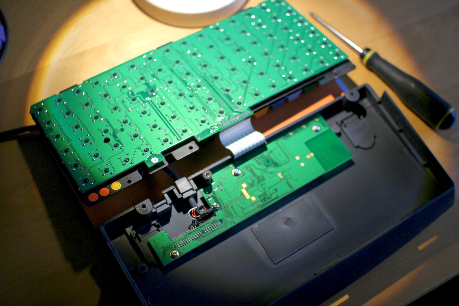
- overview.jpg (164.18 KiB) Viewed 7481 times
- detail.jpg (50.05 KiB) Viewed 7481 times
We tried to configure the matrix with QMK, but when flashed with the software, it did nothing. Not sure what the problem is. We then tested a little teensy program that can read if a key is pressed. We might now just write our own keyboard controller, just as a learning experience.
We did not remove any controllers or cut any traces. We'll find out if that will cause any problems.
-
Dilettant
- Location: Germany
- DT Pro Member: -
I've now used the keyboard for several weeks successfully with a very simple firmware I wrote from scratch. Typing works flawlessly so far. No need to cut or desolder anything. Everything is still connected to a breadboard – the challenge is now to put back everything into the case.
- breadboard-connected.jpg (198 KiB) Viewed 7152 times
-
lingex
- Location: China
- Main keyboard: logitech G610
- Main mouse: logitech G500s
- Favorite switch: MX
-
Findecanor
- Location: Stockholm, Sweden
- DT Pro Member: 0011
Awesome! How did you load the firmware onto the controller?lingex wrote: 17 Feb 2021, 14:09 I reprogram it instead of replacing the controller.
https://github.com/lingex/G610Rebuild
-
lingex
- Location: China
- Main keyboard: logitech G610
- Main mouse: logitech G500s
- Favorite switch: MX
That's easy, just a SWD port sitting there.Findecanor wrote: 17 Feb 2021, 18:08Awesome! How did you load the firmware onto the controller?lingex wrote: 17 Feb 2021, 14:09 I reprogram it instead of replacing the controller.
https://github.com/lingex/G610Rebuild
https://github.com/lingex/G610Rebuild/b ... loader.png
the other side
https://github.com/lingex/G610Rebuild/b ... K%20IO.png
-
Dilettant
- Location: Germany
- DT Pro Member: -
Ah, that's what those "pins" are for! I've no idea whatsoever about serial wire debug ports. What kind of hardware do you need on the other end?lingex wrote: 18 Feb 2021, 02:21That's easy, just a SWD port sitting there.
https://github.com/lingex/G610Rebuild/b ... loader.png
the other side
https://github.com/lingex/G610Rebuild/b ... K%20IO.png
-
lingex
- Location: China
- Main keyboard: logitech G610
- Main mouse: logitech G500s
- Favorite switch: MX
You'll need a ST-LINK (cheap) or a J-Link on the other end.Dilettant wrote: 18 Feb 2021, 09:27Ah, that's what those "pins" are for! I've no idea whatsoever about serial wire debug ports. What kind of hardware do you need on the other end?lingex wrote: 18 Feb 2021, 02:21That's easy, just a SWD port sitting there.
https://github.com/lingex/G610Rebuild/b ... loader.png
the other side
https://github.com/lingex/G610Rebuild/b ... K%20IO.png
N=NRST, C=SWCLK, D=SWDIO, G=GND, V=VCC, T=serial TX, and the last G means GND too.