Page 1 of 2
Space Invaders handwired numpad
Posted: 02 Nov 2015, 09:53
by gogusrl
Since the linear space invaders Ampex looks like more trouble than it's worth to convert and I still have the space invaders itch I've decided to try to handwire a numpad in an ibm case. Not gonna ruin the Ampex (yet), got another one that's been in storage for a while.
This is the IBM Numpad :

This is the donor board :

Can't really see it in the pic but it's a perfect fit.

The problem is that space invaders have 4 pins, how do I wire them in a matrix ?
Posted: 02 Nov 2015, 12:43
by Muirium
Got a multimeter?
You don't need to use all 4 pins. All you're looking for is a pair that clearly switches on and off while pressing the switch.
I don't think these switches have internal diodes, but it's also worth testing for those with your continuity meter. If you find a pair of pins that conducts one way, but not the other, then you've already got all the diodes in place for your matrix! If not, well, welcome to the club.
I sneakily tried the same thing with MX:

"Integrating" diodes in the switches makes the matrix wiring cleaner underneath.
 http://deskthority.net/post253057.html#p253057
Posted: 02 Nov 2015, 19:38
by gogusrl
The diodes are on the pcb, and the pins are paired 2 by 2. Thinking to wire the diodes on one pair and the matrix on the other. Would that work ?

edit : the stabbed switches have a small "lip" that snaps to the stab wire, that's why they're in a different bag (together with the yellow one from the spacebar which actually is a white as well with a small yellow dot on it and stiffer spring).
Posted: 03 Nov 2015, 19:38
by gogusrl
Progress :

Posted: 03 Nov 2015, 20:47
by Muirium
Link the full res pictures, I'll get a headache from these!
Posted: 03 Nov 2015, 20:58
by gogusrl
Click on them, they're thumbnails. the code looks like this {url=imgur.jpg}{img}imgurm.jpg{/img}{/url}. The lowercase "m" makes the photo a thumbnail but the link goes to the full res pic.
Posted: 03 Nov 2015, 21:02
by Muirium
Why bother? Thumbnails are satanic! A relic from the 56k dialup days.
(Before 56k, people wouldn't even upload a fullsize picture to the internet. It would take all night and half the next day!)
Posted: 03 Nov 2015, 21:06
by gogusrl
This is from my early days of posting on different forums, each with their own limit on size / res, some resize them some don't, and other quirks like that. I got used to this and I never use the forum's attachment system, just host everything on imgur.
anyway, more pics (tried to host them on deskthority, got "The file is too big, maximum allowed size is 1 MiB.")

They look weird with caps on because the plate is angled a bit (still need to do more filling).


Here you can see the amount of space I have for wiring and the teensy, I need some suggestions on what to do on the backside. Can I do numpad + soarer's 2in1 and throw a ps/2 connector in that space and present both the soarer and numpad to the computer at the same time ?

Posted: 03 Nov 2015, 21:11
by Muirium
Your picture, still on Imgur:
Do that please. Thumbnails really do make my eyes sore. I like to view things in place, all at once, like it's this century, instead of the last one still hiding across a bunch of tabs.
Back on topic, what's actually going on here? Where'd the plate come from? Hacksaw?
Posted: 03 Nov 2015, 21:18
by gogusrl
Fixed the pics, you can remove yours to save some space

Yeah, i used a angle grinder (thanks Compgeke for the name), you can see the original state of the plate in the OP. Also, I edited more pics in my last post.
Posted: 03 Nov 2015, 21:19
by Muirium
Much better! Thanks. Looks solid progress too. How does it handle? And did you figure out the pins you need to use?
Posted: 03 Nov 2015, 21:23
by gogusrl
Hard to say yet because it wobbles in the case but they feel pretty great.
The pins are paired 2 by 2 or you might say redundant.
Can I wire the diodes on one pair and do the matrix on the other pair ?
Check out how the pins are connected.

Posted: 03 Nov 2015, 21:38
by Muirium
You want this:
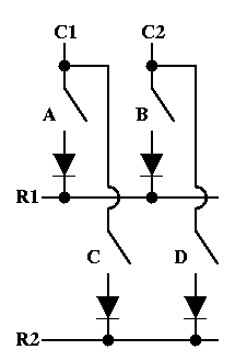 http://www.dribin.org/dave/keyboard/one_html/
Each switch needs a diode attached to it. Everything runs in parallel. So the diodes all need to be hooked directly to a row. It's harder to explain in words than pictures, but I don't think those double switches are going to help you simplify your matrix any. Because if a diode is getting cut off by another switch (serial wiring) everything breaks.
Re: Space Invaders handwired numpad
Posted: 04 Nov 2015, 06:00
by neverused
You pretty much need to ignore a pair of leads on each switch. If you put the diodes (which essentially prevent the flow of current in one direction) on one pair and the matrix on the other, the current will essentially bypass the diodes and flow across multiple switches during use. Think of it as the path of least resistance.
Posted: 05 Nov 2015, 14:39
by gogusrl
Perfect fit :


Posted: 07 Nov 2015, 15:54
by gogusrl
So much fail


Posted: 07 Nov 2015, 16:02
by Muirium
Yeah, you did it in serial. Totally wrong. Look at the diagram: parallel!
Also Matteo's hand wired matrix guide:
http://deskthority.net/workshop-f7/brow ... t6050.html
Posted: 07 Nov 2015, 18:26
by gogusrl
I should start selling my soldering skills

Posted: 07 Nov 2015, 18:40
by Muirium
Looks better now! Ready to hook up a controller?
Posted: 07 Nov 2015, 18:46
by gogusrl
Yeah, trying to figure out how to compile tmk's firmware. Once I have that, I'll figure out the pins on the pro micro and wire it up.
I'm trying to build the default lightpad fw since it's a numpad already but I'm bumping into this error :
http://i.imgur.com/KPXug5e.png
Posted: 07 Nov 2015, 18:49
by Muirium
I fail at TMK. So I always use Soarer's controller instead.
Posted: 07 Nov 2015, 19:12
by gogusrl
got it to work on linux. now I gotta change it up a bit, flash it and wire it all up.
Posted: 07 Nov 2015, 20:18
by gogusrl
Can't figure out how to change the dependencies on tmk so my shit compiles, can't figure out how to configure soarer's.
i wanna punch things right now
Posted: 07 Nov 2015, 20:45
by Muirium
I can help with Soarer's. Where are you stumbling? Trouble understanding the config file syntax or are you still figuring out how to use scas and scwr?
Posted: 07 Nov 2015, 20:49
by gogusrl
Trying to figure out the syntax.
I wanna do
Numlock, /, *, something_here
7,8,9,-
4,5,6,+
1,2,3
0, ., enter
Code: Select all
    # Numpad

    matrix
       scanrate 1
       debounce 5
       blocking 0

       sense         PF7         PB6        PB5          PB4
       strobe   PF0  NUM_LOCK    PAD_SLASH  PAD_ASTERIX  PAD_EQUALS
       strobe   PF1  PAD_7       PAD_8      PAD_9        PAD_MINUS
       strobe   PF4  PAD_4       PAD_5      PAD_6        PAD_PLUS
       strobe   PF5  PAD_1       PAD_2      PAD_3
       strobe   PF6  PAD_0       PAD_PERIOD PAD_ENTER
    end
Hope this works

Posted: 07 Nov 2015, 21:14
by Muirium
Looks about right. But are you sure it matches your matrix?
Posted: 07 Nov 2015, 23:37
by gogusrl
ok, I managed to flash the firmware and install the required libraries for the sc"suite" but I'm getting
Code: Select all
/scinfo
scinfo v1.10
scinfo: looking for Soarer's Converter: not found

Posted: 08 Nov 2015, 01:12
by Muirium
Well, I've no idea what you're seeing there. "Error while loading shared libraries"? What the fuck is that about? Are you on Linux?
I do everything on Mac OS X. Right now I'm on my Kishsaver, so no Soarer connected. This is what scinfo says:
./scinfo
scinfo v1.10
scinfo: looking for Soarer's Converter: not found
Simple. And nothing about shared libraries. I've no idea what's going on with you though.
Posted: 08 Nov 2015, 01:44
by gogusrl
Managed to flash the firmware properly and upload the config but only the "3", "+" and "-" keys are working in the correct position. Everything else is dead. This is the config I flashed :
Code: Select all
    matrix
       scanrate 1
       debounce 5
       blocking 0

       sense         PB6         PB2        PB3          PB1
       strobe   PD7  NUM_LOCK    PAD_SLASH  PAD_ASTERIX  PAD_EQUALS
       strobe   PC6  PAD_7       PAD_8      PAD_9        PAD_MINUS
       strobe   PD4  PAD_4       PAD_5      PAD_6        PAD_PLUS
       strobe   PD0  PAD_1       PAD_2      PAD_3
       strobe   PD1  PAD_0       PAD_PERIOD PAD_ENTER
    end


Posted: 08 Nov 2015, 01:55
by Muirium
Ugh, Pro Micro. (Use a real Teensy!) There's a translation chart kicking around DT somewhere with what pin equals what for that awkward thing. I only ever used one for a converter, and it even flaked out at that…