Being able to sense key-up events is really important.
I've been trying to think for some time now about how to do this by strobing power. Some analog sensing may be to way to do it. The trouble is that, when you strobe power to these "pulse low" sensors, you only see a low pulse as voltage is ramping up, when it is at 2.5 V. With digital sensing, depending on the "static disciple" (e.g. when you call a voltage a "0" or a "1"), this could be tricky.
The algorithm to sense a "pulse low" switch using power strobing may require analog sensing. It would look something like this:
- Power the switch on
- Wait for the voltage from the switch to reach 2V
- Once the voltage has reached 2V: does it ever go back below 2V, even if only for a single sample? If so, the switch is pressed.
- Time out after 2.25 ms. This gives a 444 Hz polling rate.
Looking at the ATmega32U4 data sheet it looks like, with V_cc = 5V, V_IH's low threshold is 1.9 V which means I can use digital inputs. Using all of Port B and Port D for input (16 pins), I can use Port C and Port E to drive a mux to turn on power to groups of 16 switches at a time. That gives about a 100 Hz polling rate for a matrix with up to 64 keys, or a 50Hz polling rate for a matrix with up to 128 keys.
The "hold low" switches can be strobed as quickly as the MCU can manage.
But again: a retrofit would allow me to get the existing, terrible, 1KRO, press-only functionality that the board had when it was made. This might be good enough for typing if I only need one or two modifiers. Anything better will likely require a new PCB, new sensors, or both. I'm thinking new sensors are the way to go at this point.
I'd rather not do this in analog. That sounds like a lot of code for the first case, and perhaps not terribly accurate in the second case. If I was able to get the raw position from the sensors then perhaps.
Honeywell Micro Switch Reverse Engineering and Conversion thread
-
HuBandiT
- Location: Budapest, Hungary
- Main keyboard: notebook built-in with goodness between G, H and B
- Main mouse: pointing stick with a red dot, between G, H and B
- Favorite switch: (newbie - jury is still out)
- DT Pro Member: 0123
Well, I think you can get away without it for regular, 70s style typing. But I agree in modern GUI environments it is pretty much a requirement to properly use hotkey combinations.
Have you checked how the power consumption of the switch changes? If it reliably depends on pressedness, that might also offer way for sensing. Float the GND and power lines a bit, and then measure them back with an ADC, to infer whether the key is still pressed. Contrived still.
You would only ever need (want?) to power-strobe the keys that you know are currently pressed (which in most cases won't be more than 6-8-10), since the others are known to be up. That would make your scanning faster. You keep the unpressed switches powered normally, and only "scan" (well, poll - by power-strobing) the pressed ones. Still means a new PCB.
Yeah, obviously the least nightmare would be using non-momentary sensors. But that would also kinda rob (at least part of) the soul of the board. Plus then you still only have 1KRO (although you know when that one key was released). For more you either go 1×N "matrix" (multiplexing at the microcontroller end, if needed), or do some kind of active matrix, where the output of a hall sensor is only passed through to the row/column line when it's column/row line is addressed. Both of which seemingly will need a new PCB (or large amounts of trace cutting and splicing with air wires).
-
XMIT

- [ XMIT ]
- Location: Austin, TX area
- Main keyboard: XMIT Hall Effect
- Main mouse: CST L-Trac Trackball
- Favorite switch: XMIT 60g Tactile Hall Effect
- DT Pro Member: 0093
The whole "soul of the board" argument sort of went out the window when I discovered that the board was possessed! Seriously, it's going to take some hardware hacking regardless.
Part of my goal was to enable others with these boards to do something - anything - with them. So there is some value into getting the existing electronics hobbling along in some form or another (hi Firebolt1914!). That's probably the approach I'll take for now even if the result is mediocre.
I do have other Hall boards that are perhaps more friendly for hacking, like the Diablo board or perhaps my TI 914 board. I may spin a new PCB, though. We'll see.
Last edited by XMIT on 15 Dec 2016, 05:50, edited 1 time in total.
-
HuBandiT
- Location: Budapest, Hungary
- Main keyboard: notebook built-in with goodness between G, H and B
- Main mouse: pointing stick with a red dot, between G, H and B
- Favorite switch: (newbie - jury is still out)
- DT Pro Member: 0123
Sure thing. Enjoy! And holler if you want to collaborate on cobbling together an ADC-based 0.5KRO (well, it doesn't sense release, does it?  ) controller.
-
XMIT
- [ XMIT ]
- Location: Austin, TX area
- Main keyboard: XMIT Hall Effect
- Main mouse: CST L-Trac Trackball
- Favorite switch: XMIT 60g Tactile Hall Effect
- DT Pro Member: 0093
I'm working on ways to perform actual sensing using these various Hall sensors in various configurations. Now that I've got ohaimark's board from our Dallas trip I'm re-motivated to work out techniques for these unique boards.
In general, I'll do protocol conversion and/or controller retrofitting to the existing cable when possible, to make this work as accessible as possible to people who have these boards and want to use them.
1KRO with either pulse-low or hold-low switches is pretty trivial. Just wire up a matrix. Whenever a row and a column pin go low, detect a key press. This can even be done as an interrupt service routine on a microcontroller. Nothing to it, and, this will unblock work on the Wang board.
With clever design (similar to what some rubber dome membranes use) I might be able to achieve something like 2KRO with two separate matrices.
The best I can tell for the NKRO case requires some additional hardware. One is using a transistor - like a 2N3906 - for each and every position. This turns a Hall sensor into something that looks like a mechanical switch to a matrix sensing algorithm. As an example of how to use a 2N3906:
https://learn.sparkfun.com/tutorials/tr ... i-switches
The idea is to somehow only enable one row or one column at a time to be sensed. Mechanical key switch matrices accomplish this by using one for strobing and one for sensing. By only strobing one row or one column at a time, in effect only one is being selected. So, strobing power becomes a way of selecting a row or column of sensors at a time. That could be suitable for an NKRO retrofit.
With the pulse low switches, we need to see if any keys were pressed even for an instant within some amount of time. The algorithm could be something like:
- enable a row, turning on power to an entire row of switches;
- scan them for 5ms, AND'ing together all the results;
- at the end of 5ms, read the AND'ed results to see which keys were pressed.
-
XMIT
- [ XMIT ]
- Location: Austin, TX area
- Main keyboard: XMIT Hall Effect
- Main mouse: CST L-Trac Trackball
- Favorite switch: XMIT 60g Tactile Hall Effect
- DT Pro Member: 0093
...that, or, use a bunch of 16-to-4 line encoders using pairs of 74148s. That would enable reading a 256-key input matrix with just 8 pins.
Something like this:
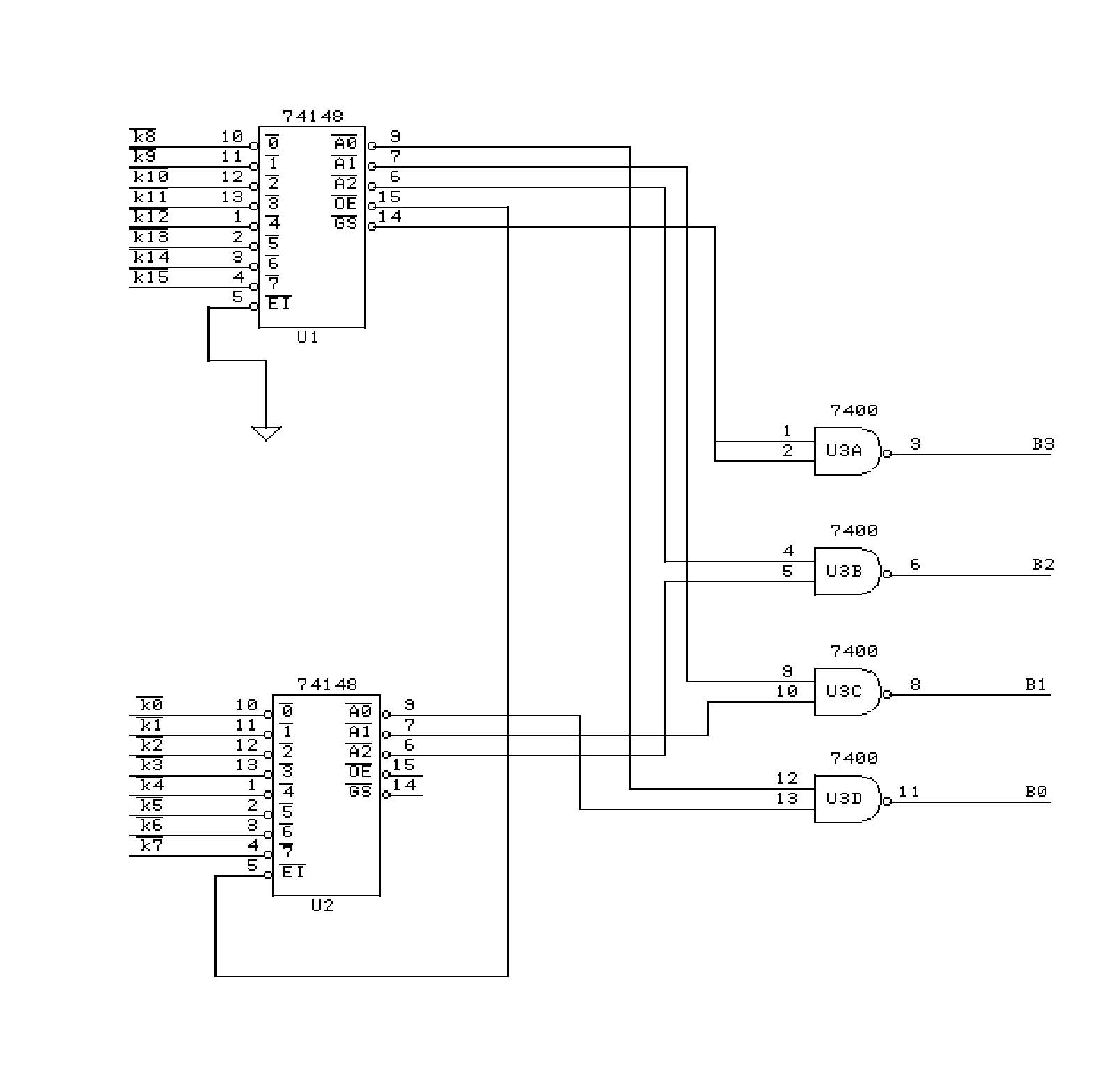
From http://denethor.wlu.ca/pc120/encoder_cascade.shtml.
Use 16 pins for the rows and 16 pins for the columns. Wire it into one input port on an MCU.
The worst-case 30ns propagation delay for the 74148 is really quite reasonable.
http://www.ti.com/lit/ds/symlink/sn54148.pdf
Something like this:
From http://denethor.wlu.ca/pc120/encoder_cascade.shtml.
Use 16 pins for the rows and 16 pins for the columns. Wire it into one input port on an MCU.
The worst-case 30ns propagation delay for the 74148 is really quite reasonable.
http://www.ti.com/lit/ds/symlink/sn54148.pdf
-
vvp

- Main keyboard: Katy/K84CS
- Main mouse: symetric 5-buttons + wheel
- Favorite switch: Cherry MX
- DT Pro Member: -
Sorry I did not read the whole thread so I'm not sure what is impact of your use of hall sensors. But there is a very nice overview of approaches to a simple matrix scanning here: http://www.openmusiclabs.com/learning/d ... -scanning/
Maybe you will find it useful. I quite like the options using shift registers. These use very little pins.
Maybe you will find it useful. I quite like the options using shift registers. These use very little pins.
-
XMIT
- [ XMIT ]
- Location: Austin, TX area
- Main keyboard: XMIT Hall Effect
- Main mouse: CST L-Trac Trackball
- Favorite switch: XMIT 60g Tactile Hall Effect
- DT Pro Member: 0093
Thanks. These are all matrix scanning techniques that assume the input is a mechanical switch with a diode in series. I'm talking about how to build that matrix, or, how to make a Hall sensor appear like a mechanical switch.
Multiplexing the strobe pins is a common trick when pins are limited.
Multiplexing the strobe pins is a common trick when pins are limited.
-
Firebolt1914
- Location: United States
- Main keyboard: IBM SSK
- Main mouse: Kensington Orbit
- Favorite switch: Buckling Spring/Thorpe
- DT Pro Member: -
Hello again! I have (ambitiously) decided to make a 60% PCB with a layout dedicated for the caps of my other hall effect boards.
Since I'm doing a custom PCB, I am going to try a method HaaTa had suggested. I'm not sure if it was mentioned in this thread before, but he discovered that after re-powering the switches, they can output again. It is possible to have the keys be 'held down' by turning them on and off quickly. Then the single output can be strobed and scanned regularly.
@XMIT, how much current does each one of these sensors draw?
I will try to keep with this project and try to learn new things for once...
-
XMIT
- [ XMIT ]
- Location: Austin, TX area
- Main keyboard: XMIT Hall Effect
- Main mouse: CST L-Trac Trackball
- Favorite switch: XMIT 60g Tactile Hall Effect
- DT Pro Member: 0093
Not enough that you really need to worry about it. From earlier:
The pull-up resisters will source more current than the switches themselves for sure.
As for my board I'm just working on putting it back together and I'll convert it as is without too much more work. Since I already have a working Hall effect board
-
dorkvader

- Main keyboard: Unicomp
- Main mouse: CST 1550
- Favorite switch: Buckling Spring over Capacitave. (Model F)
- DT Pro Member: -
XMIT and I met up recently, and he told me about this thread. so I will be cross posting my findings here from the GH thread I recently started:
https://geekhack.org/index.php?topic=87453
Basically: switches require 0.13 mA unpressed and 4mA pressed. Next, I will be driving a switch with a 100kHz square wave to see how it responds to strobing the power. I have a large pile of sensors that are of the "normal" type, thank goodness they aren't the next-to-useless pulse variant. I also want to order some transistors so I can power a whole column of switches form 1 teensy pin.
Another thing to note: connecting the power leads reversed, the switch draws about 0.5A and heats up a lot, but otherwise will continue to work once you connect it normally. I accidentally supplied reverse power to it for at least 2 minutes.
-
XMIT
- [ XMIT ]
- Location: Austin, TX area
- Main keyboard: XMIT Hall Effect
- Main mouse: CST L-Trac Trackball
- Favorite switch: XMIT 60g Tactile Hall Effect
- DT Pro Member: 0093
If you have some extra normal sensors let me know. I don't really want to spend a lot of time on the strobe type sensors. I was thinking of just making replacements myself.
-
seebart

- Offtopicthority Instigator
- Location: Germany
- Main keyboard: Rotation
- Main mouse: Steelseries Sensei
- Favorite switch: IBM capacitive buckling spring
- DT Pro Member: 0061
- Contact:
-
Slom
- Location: land of the rusty beamsprings
- DT Pro Member: -
I just found this:
http://randomvariations.com/2014/10/16/ ... -computer/
http://randomvariations.com/2014/10/18/ ... ard-logic/
First time I've found a lead on those AMI chips.
http://randomvariations.com/2014/10/16/ ... -computer/
http://randomvariations.com/2014/10/18/ ... ard-logic/
First time I've found a lead on those AMI chips.
-
Slom
- Location: land of the rusty beamsprings
- DT Pro Member: -
Ok, I have decided to go for the TI silent first. These have scan modules, with one input that can be pulled low and one output that will switch to low if the key is pressed AND the input is low. I completed a proof of concept today, connected two drive columns and one sense row. When you look at the keyboard from above, the pins in the connector are counted from the right:
My first solder job ... can only get better from here  And here's the arduino code. Note that inputs for the keyboard are outputs for the teensy and vice versa. Also note that the input has to have a input mode INPUT_PULLUP (see setup function).
Code: Select all
 Board  | Teensy | Comment
------------------------------------------------
  4     | VCC    |
  5     | GND    |
 12     | B1     | drive input for '1'
 17     | D0     | sense output for '1' and '9'
 18     | B0     | drive input for '9'
- DSC01891.JPG (929.56 KiB) Viewed 7129 times
- DSC01887.JPG (519.77 KiB) Viewed 7129 times
Code: Select all
int outputPins[] = { PIN_B0, PIN_B1 };
const int outputPinCount = sizeof(outputPins) / sizeof(outputPins[0]);

int inputPins[] = { PIN_D0 };
const int inputPinCount = sizeof(inputPins) / sizeof(inputPins[0]);

const int keyCount = inputPinCount * outputPinCount;
bool keyState[keyCount];

unsigned int keys[keyCount] = { KEY_9, KEY_1 };

void setup()
{
  for (int outputIndex = 0; outputIndex < outputPinCount; outputIndex++)
  {
    pinMode(outputPins[outputIndex], OUTPUT);
    digitalWrite(outputPins[outputIndex], HIGH);
  }

  for (int inputIndex = 0; inputIndex < inputPinCount; inputIndex++)
  {
    pinMode(inputPins[inputIndex], INPUT_PULLUP);
  }

  for (int keyIndex = 0; keyIndex < keyCount; keyIndex++)
  {
    keyState[keyIndex] = false;
  }
}

void loop() {

  for (int outputIndex = 0; outputIndex < outputPinCount; outputIndex++)
  {
    digitalWrite(outputPins[outputIndex], LOW);
    delayMicroseconds(15);

    for (int inputIndex = 0; inputIndex < inputPinCount; inputIndex++)
    {
      int keyIndex = (outputIndex * inputPinCount) + inputIndex;
      bool newState = !digitalRead(inputPins[inputIndex]);
      if (newState != keyState[keyIndex])
      {
        if (newState)
        {
          Keyboard.press(keys[keyIndex]);
        }
        else
        {
          Keyboard.release(keys[keyIndex]);
        }
        keyState[keyIndex] = newState;
      }
    }

    digitalWrite(outputPins[outputIndex], HIGH);
  }
}

-
Slom
- Location: land of the rusty beamsprings
- DT Pro Member: -
I completed the conversion yesterday (safe for the mechanical toggle switches and the LED):
post398120.html#p398120
I will do a proper write-up once I find some time. First I have to decide where to put the source code. Another open point is checking whether the second TI Silent I have shares the same matrix and pin-out.
I should also mention that your work was a great inspiration. Thank you so much!
-
XMIT
- [ XMIT ]
- Location: Austin, TX area
- Main keyboard: XMIT Hall Effect
- Main mouse: CST L-Trac Trackball
- Favorite switch: XMIT 60g Tactile Hall Effect
- DT Pro Member: 0093
I'm really excited to see some progress here!
It doesn't look like this year is going to be any better than last for me making any progress here. But if I do I'll post updates  .
.
It doesn't look like this year is going to be any better than last for me making any progress here
-
dorkvader
- Main keyboard: Unicomp
- Main mouse: CST 1550
- Favorite switch: Buckling Spring over Capacitave. (Model F)
- DT Pro Member: -
Slom wrote:I completed the conversion yesterday (safe for the mechanical toggle switches and the LED):
post398120.html#p398120
I will do a proper write-up once I find some time. First I have to decide where to put the source code. Another open point is checking whether the second TI Silent I have shares the same matrix and pin-out.
I should also mention that your work was a great inspiration. Thank you so much!
Wow thanks for posting this! I was reading your post and saw this:
If you can indeed use one of the center pins to turn the output off like that, then you could get NRKO without a PCB swap, which is HUGE! I actually have one or two of that exact keyboard, and one other TI Silent 700 that is completely different despite the fact that they are both from 1979. It only has a 1 layer PCB and I already drilled it for re-wiring, but that's an easy fix.These have scan modules, with one input that can be pulled low and one output that will switch to low if the key is pressed AND the input is low.
I'm going to hook my test switch up (which I'm currently turning on and off at 2MHz to see what happens) and see if I can validate that.
I'm sort-of in the same boat as XMIT here. I'm taking classes in EE while also working full time, and I spend about 20 hours per weekend on lab reports, so there's not going to be much progress from me until Summer hits and I'm "only" working 40h/week.
In the meantime I wrote up some hall effect sensing and wiring ideas, which is completely outdated by the above claim.
workshop-f7/hall-effect-keyboard-sensin ... ml#p398665
edit: I have some foreign keycaps for my TI Silent 700 board (no idea what they were doing on a KB in the USA). I would happily mail them to you wherever you're located in exchange for helping us get our KB working like yours I have Å Ä Ö which I saw on your modern keyboard on your laptop.
-
Slom
- Location: land of the rusty beamsprings
- DT Pro Member: -
This only applies to the "scan module" type of SD switches. These with a 'S' as last character in the part number.dorkvader wrote:
Wow thanks for posting this! I was reading your post and saw this:If you can indeed use one of the center pins to turn the output off like that, then you could get NRKO without a PCB swap, which is HUGE! I actually have one or two of that exact keyboard, and one other TI Silent 700 that is completely different despite the fact that they are both from 1979. It only has a 1 layer PCB and I already drilled it for re-wiring, but that's an easy fix.These have scan modules, with one input that can be pulled low and one output that will switch to low if the key is pressed AND the input is low.
I'm going to hook my test switch up (which I'm currently turning on and off at 2MHz to see what happens) and see if I can validate that.
The pins are: +5V, OUT (sense), IN (strobe), GND
On the TI silent you can see which pins are IN and GND by looking at the shift and control keys. For those keys GND and IN are connected on the pcb, which means that the switches are always active.
As I said above, my conversion only works for those "scan module" types of switches. All the hold low/pulse low switches still need some other method, and for those your write up is still very much valid. So I would strongly contest this "completely outdated"dorkvader wrote: In the meantime I wrote up some hall effect sensing and wiring ideas, which is completely outdated by the above claim.
workshop-f7/hall-effect-keyboard-sensin ... ml#p398665
No, that is not necessarydorkvader wrote: edit: I have some foreign keycaps for my TI Silent 700 board (no idea what they were doing on a KB in the USA). I would happily mail them to you wherever you're located in exchange for helping us get our KB working like yours I have Å Ä Ö which I saw on your modern keyboard on your laptop.
-
dorkvader
- Main keyboard: Unicomp
- Main mouse: CST 1550
- Favorite switch: Buckling Spring over Capacitave. (Model F)
- DT Pro Member: -
Hey guys, I have been able to confirm slom's results with my copy of the board he used (from a silent 700). If Pin1 is VCC, pin 2 is output pin3 is what I'll call output control and pin4 is ground. When connected to power, output control pin shows about the same as vcc and pressing the switch, nothing happens. power draw does not change and no output is detected, When the output control pin (which is about the same as vcc when floating) is connected to ground, the switch acts normally, and power draw goes up by a little when it's pressed, and you get close to VCC on the output.
I did not have time to get decent scope shots or experiment photos since this was just a quick test. I'm also unsure if all switches or keyboards with the "s" designation operate in this way. However you should be able to identify keyboards that do by the following features
1. If 2 pins are connected together, they are the lower one (output control) and ground. This results in a switch which is always active. Look for modifiers, like "shift" which are wired this way in this keyboard
2. If you have a DMM, put 5V to pin 1 and 4, then measure 0V on pin 2 and ~5V on pin 3. Note that the switches have maximum ratings up to about 30V, so if you "only" have a 12V wall wart (or a 9V battery), then you can try with it. Pressing the switch nothing will happen at pin 2, and if you bridge pin 3 and 4 (output control to ground) you will now get ~5v at pin 2 when pressed.
*note* Right now I think that keyboards which have the inner 2 pins tied together will *not* support this technique. Also my 1977 keyboard with tripleshots ( https://www.flickr.com/photos/dork_vade ... 9601264430) definitely does not either, because I have fully reverse engineered that keyboard
What is next? now that we have a keyboard confirmed to work with an output control pin, we can characterize it further. I will feed a square wave into the output control pin and see how "fast" it turns the output on/off I strongly suspect it's faster than powering/depowering the switch entirely and using this we can achieve a 100KHz scanrate (or better?) Using the power pin to control output on/off we can only reliably use a scanrate of perhaps 40 kHz or so. Also looking at the shape of the waveform as we turn the output on/off with the output control pin will be good.
But now that the underlying mechanic has been tested and verified by two people, we can start converting these keyboards to USB very easily using normal sense/scan techniques. Debouncing is likely not needed but that remains to be seen. And then "because we can" we can crank the scanrate up to 100KHz and have proper "gaming" switches from the 1970's.
I'll work on my homework today and if I get a chance, I'll solder up a quick test fixture on a switch with a pull-up resistor and post some preliminary results. Note that due to the much higher input impedance of my DMM (over 10 MΩ) a pull up resistor was not necessary to test the switch, but it is required for a 50 Ω impedance of my scope. This is why I have no scope shots for now. Discerning the switch you can "see" it rise up, but not enough for proper characterization. Then I'll write up a post and put it on GH and DT but I get better feedback here, so I might make the switch to being primarily on DT's workshop forum than GH's MST.
That's all for now. Very exciting news and many thanks to slom for reporting on this.