Page 11 of 58
Posted: 21 Feb 2014, 15:04
by ماء
Posted: 21 Feb 2014, 16:24
by Muirium
BimboBB wrote:pasph wrote:i would love "the full MU" but i don't think there's love for big kbs
thats not true....i love them all.

"the full MU" remembers me a bit of this WYSE terminal board, which layout i always found to be quite nice (okay....the spacebar/mod sizes are maybe a bit over the top
)

Thanks! My motivation is to get the home row horizontally centred on the board. I forever shuffle my IBMs around with the numpads hanging over at the right, and even my SSK and TKLs wind up asymmetric: because my hands want to line up with the centre of my screen. Just seems to come naturally to me. My 60% is almost perfect, but I want to bring the same goal to something bigger.
I could definitely add those two keys to my µTKL (or should I call it TenMuLess?) to achieve the wall of caps: a look I really like. That way there's a whole load of programmable keys in a smart rectangular block over there, like your own integrated mini Tipro. (Which reminds me, I'm still half way through my Tipro++ project…) As for F1-F12, do not fear: they are right across the top of the keyboard (Fn+5 = F5, Fn+MINUS = F11 etc. just like an HHKB or my 60%) or indeed on the numpad if you prefer.
I still owe ماء a symmetric design. Perhaps I'll try one with standard (Round 5) caps and fitting it within the same footprint. I've no idea what to do with TrackPoints, though. I think I'd rather have a trackball in the centre…
Posted: 21 Feb 2014, 17:54
by scottc
Muirium wrote:As for F1-F12, do not fear: they are right across the top of the keyboard (Fn+5 = F5, Fn+MINUS = F11 etc. just like an HHKB or my 60%) or indeed on the numpad if you prefer.
I was talking about the lack of a Fn key in the muTKL when talking about F1-F12, it's not there! I assume it's meant to be in the usual HHKB-like spot?
Posted: 21 Feb 2014, 18:30
by matt3o
I was looking into the screws to hold the layers and I found these

they look pretty nice but they are too short. wondering where we could find some nice screws
Posted: 21 Feb 2014, 18:41
by rindorbrot
Those screws look pretty cool.
There should be longer ones available, as they are for example used to keep two pieces of funiture together.
Posted: 21 Feb 2014, 18:47
by matt3o
look at these babies

it seems they are called "chicago screws" or "sex bolts"
Posted: 21 Feb 2014, 19:02
by sean4star
Another one for symmetry.
 keyboard-layout-editor
Note the 1.5 right shift. I wanted to leave the arrow keys isolated.
Posted: 21 Feb 2014, 19:09
by mohitgarg
Have you looked at the method I use for my acrylic cases for a clean top and bottom?
I use hexagonal standoffs and then use two small flat head screws, one on top and one on bottom. Check the GHPad thread on GH, it has some information on this.
http://geekhack.org/index.php?action=dl ... 8684;image
http://geekhack.org/index.php?topic=389 ... msg1093656
I've done quite a bit of research for the acrylic cases, finding the right post-screws/sex-bolts can be very hard, and also requires a thicker bevel.
Posted: 21 Feb 2014, 19:27
by matt3o
very nice but your hole section is conic. I can't do that on stainless steel. I might be able to do that on aluminum, but not steel
Posted: 21 Feb 2014, 19:33
by Muirium
scottc wrote:Muirium wrote:As for F1-F12, do not fear: they are right across the top of the keyboard (Fn+5 = F5, Fn+MINUS = F11 etc. just like an HHKB or my 60%) or indeed on the numpad if you prefer.
I was talking about the lack of a Fn key in the muTKL when talking about F1-F12, it's not there! I assume it's meant to be in the usual HHKB-like spot?
Well spotted. I'd say you're paying too much attention to the legends, but the fault is mine: that little Fn key shouldn't go missing.
In practice, like on the Model M I'm on just now, I use Caps Lock as my function key habitually when not on my custom. (That's now latching Function Lock!) So sometimes I forget…
Posted: 21 Feb 2014, 19:44
by pasph
matt3o wrote:look at these babies
it seems they are called "chicago screws" or "sex bolts"
I like them!
Posted: 21 Feb 2014, 19:46
by matt3o
pasph wrote:it seems they are called "chicago screws" or "sex bolts"
I like them!
if you can find them of the right height...
Posted: 21 Feb 2014, 19:51
by sean4star
matt3o wrote:pasph wrote:it seems they are called "chicago screws" or "sex bolts"
I like them!
if you can find them of the right height...
I think it would be pretty easy to cut them down to size with a dremel. Just get them a tad too long.
Posted: 21 Feb 2014, 20:02
by mohitgarg
matt3o wrote:
very nice but your hole section is conic. I can't do that on stainless steel. I might be able to do that on aluminum, but not steel
Says who? The holes are not counter-sunk, instead they are a shade smaller than the flat-heads, this allows for the flat-heads to just sit in flat. Making counter-sunk holes in acrylic is quite hard.
Posted: 21 Feb 2014, 20:09
by matt3o
mohitgarg wrote:matt3o wrote:
very nice but your hole section is conic. I can't do that on stainless steel. I might be able to do that on aluminum, but not steel
Says who? The holes are not counter-sunk, instead they are a shade smaller than the flat-heads, this allows for the flat-heads to just sit in flat. Making counter-sunk holes in acrylic is quite hard.
I'm sorry, I'm not sure I understand.
from this picture
http://i.imgur.com/IEsReUM.jpg it seems the holes are counter-sunk. You mean that they are just "stepped"?
Posted: 21 Feb 2014, 20:15
by mohitgarg
The holes are just a little smaller than the the head of the flat head screws, so it sits almost flush (Not entirely), so it cna be cut using a laser.
Eg, for M3 screws, the screw row is 3mm in diameter, the head is 5mm, so the screw holes on top and bottom layer are 4.7mm.
The hex standoff in the middle layer keeps the screws aligned properly. For layers that will not have the standoffs (I generally use 8mm standoffs as they are easiest to find) and are neither the top/bottom layer, the screw holes are the diameter of the screw rod.
Posted: 21 Feb 2014, 20:28
by matt3o
okay, so the first layer is held by friction of the screw head?
Posted: 21 Feb 2014, 21:01
by mohitgarg
No, if you see from my example, the head of the screw is 5mm, the hole on the top and bottom layer is 4.7mm, thus .15mm of the screw and layer overlap, which is enough to keep the layers held together.
Posted: 21 Feb 2014, 21:28
by pasph
matt3o wrote:pasph wrote:it seems they are called "chicago screws" or "sex bolts"
I like them!
if you can find them of the right height...
What is the right height?
Posted: 21 Feb 2014, 21:31
by pasph
Just for fun


Posted: 21 Feb 2014, 22:09
by Muirium
The HyperPasph?
Anyway, here's that wall of Tenkeyless I was talking about. See what I did with the numpad?

- TenMuLess.png (126.92 KiB) Viewed 6342 times
The downside: it's not exactly symmetrical. Technically, it's a sliver better than a standard TKL, though. And a ton compared to a traditional full size layout.
Re: R: Group Build prototyping phase
Posted: 21 Feb 2014, 22:26
by pasph
Muirium wrote:The HyperPasph?
Sacrilege!
Burn the 7bit infidel!
Posted: 21 Feb 2014, 22:59
by sean4star
Muirium wrote:The HyperPasph?
Anyway, here's that wall of Tenkeyless I was talking about. See what I did with the numpad?
TenMuLess.png
The downside: it's not exactly symmetrical. Technically, it's a sliver better than a standard TKL, though. And a ton compared to a traditional full size layout.
Why not add a block of grey F-keys on the left?
A 3x4 block leaving 3 black keys on the bottom row.
Posted: 21 Feb 2014, 23:18
by Muirium
I do in fact have another draft layout exactly like that.
Its disadvantage would be its size. Or advantage, depending on preference. I estimate that it would weigh significantly more than my >1 kg shiny 60%, while remaining comparatively compact.
Rather than function keys, I'd probably put one of these on it:

In fact, here we go: meet the family, all to scale.

- The Family Mu.png (609.16 KiB) Viewed 6307 times
(Spot the error? 15,18 and 21 units wide! Silly manual legends.)
Posted: 21 Feb 2014, 23:31
by CJNE
sean4star wrote:
I think it would be pretty easy to cut them down to size with a dremel. Just get them a tad too long.
They are beautiful
An option could be to only get the "female" parts and have a threaded rod that you cut to appropriate length, if you can't find long enough screws.
Posted: 21 Feb 2014, 23:36
by CJNE
Muirium wrote:
In fact, here we go: meet the family, all to scale.
Is there a µ60% ansi sibling? I.e a mix between µ60% ISO and TenMuLess (TenMuMoreLess?)
Posted: 21 Feb 2014, 23:44
by Muirium
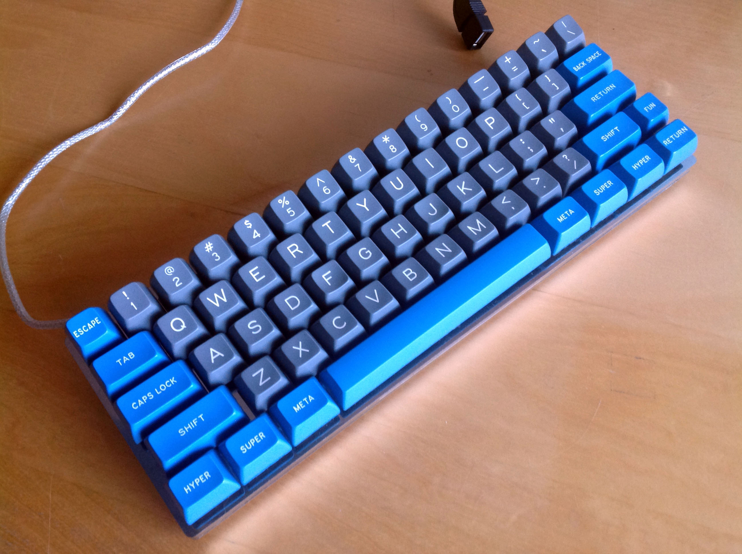
Of course…

- µ60%.png (109.46 KiB) Viewed 6293 times
Which I happen to have on my desk right here!
 (Much to Snoopy's frustration, as I show it off every day or two.)
Posted: 21 Feb 2014, 23:50
by CJNE
That's the one! Count me in for at least one of those
Posted: 21 Feb 2014, 23:57
by jdcarpe
I was thinking something like this? With a full tenkey on the right...

Posted: 21 Feb 2014, 23:59
by Muirium
jdcarpe wrote:I was thinking something like this? With a full tenkey on the right...
Great minds, eh? I like your Cherry stabs. I've some PCB mount stabs to try out this time, too. And there may even be a few plate mount Cherry stabs available. (Note to self: pester Kbdfr about those.)
CJNE wrote:That's the one! Count me in for at least one of those
Sweet! It's a very solid little design. Looks like this from the side:
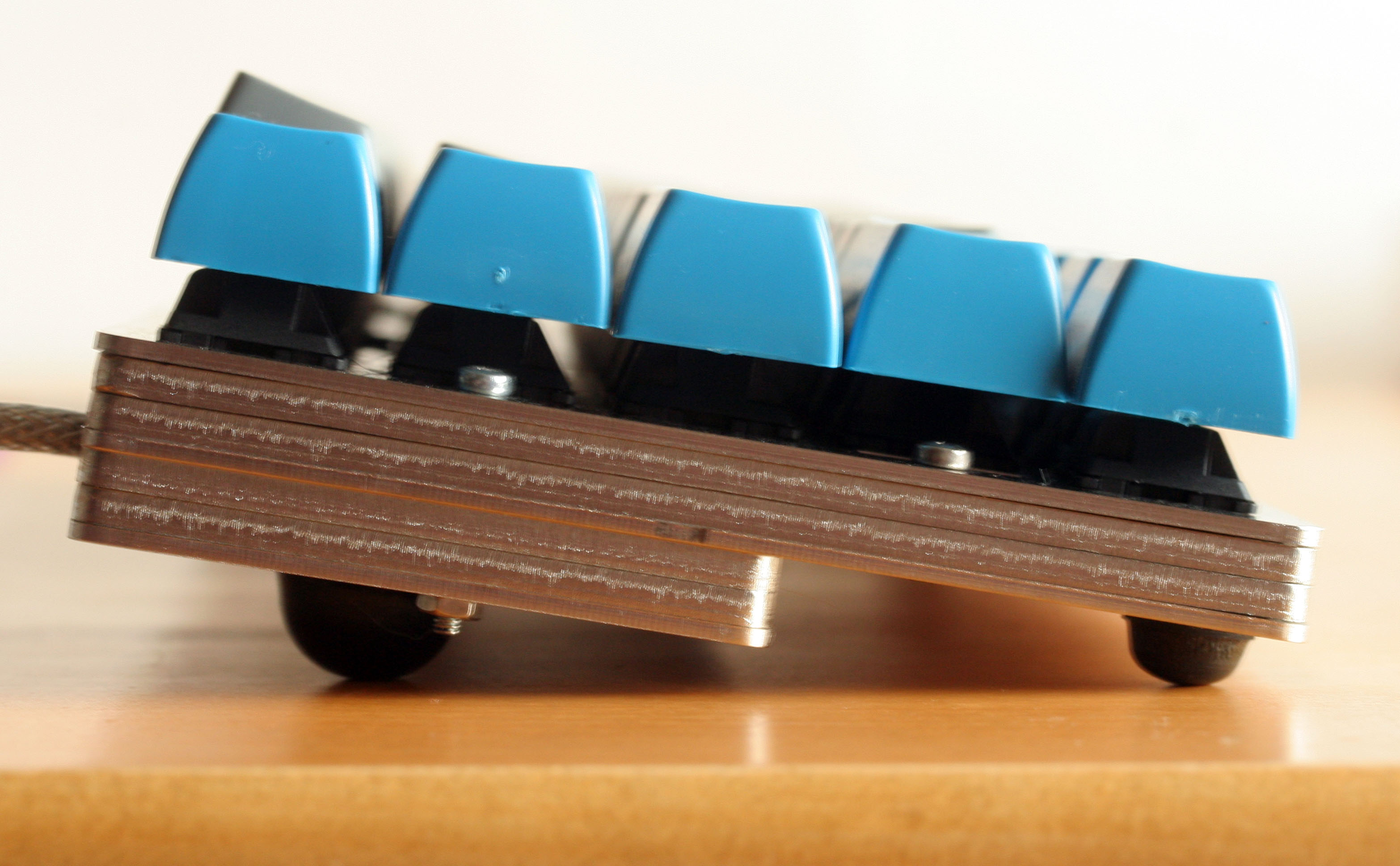 http://deskthority.net/post133887.html#p133887
Speaking of which: what's the plan for the lower layers of the cases? My 60%'s a stepped design as you can see: thicker at the back than the front. I'm thinking of trying some more of that this time.


 selling on GH $7$$$