Page 9 of 9
Posted: 26 Jun 2013, 13:40
by Muirium
matt3o wrote:I'm taking photos of the whole process, I'm finishing it right now. I'd say in a couple of hours should be ready
Grab a beverage of your choice, everyone. This ought to be informative!
Posted: 26 Jun 2013, 14:06
by suka
matt3o wrote:I'm taking photos of the whole process, I'm finishing it right now.
I expect another outstanding documentary - but judging from the assembly teaser you will not disappoint us

matt3o wrote: I'd say in a couple of hours should be ready
Yeah, that's about what it takes to wire up a matrix without PCB, I know - once you're experienced with it! It took me only 2 hours per half this time (plus another one for teensy and cabling) without producing a single error! Hope you have equal success with your fox, looking forward to seeing the results.
Posted: 26 Jun 2013, 19:57
by matt3o
Posted: 13 Oct 2014, 23:54
by stormbard
matt3o, if I wanted to add LED backlighting, what extra work would be needed?
Posted: 14 Oct 2014, 00:43
by Muirium
An LED in each switch, all wired up together (for a uniform backlight) with appropriate resistors to the main power rail on the Teensy. I'm not sure how you'd turn them on and off. And you definitely couldn't do fancy animated patterns without a whole second controller.
Has anyone actually gone ahead and backlit their own hand wired keyboard yet? I was thinking of it originally, but got into thick high end caps and forgot all about LEDs.
Posted: 14 Oct 2014, 01:13
by stormbard
Could you use the same method you you'd use to turn the LEDs for CapsLock, NumLock, and ScrollLock on and off?
Also does it not matter that the the inputs are left floating for the rows/columns? Or am I missing seeing something that is pulling them either high or low?
Posted: 14 Oct 2014, 01:27
by Muirium
The keyboard matrix is strobed and sensed. One row gets strobed (set high or low, I don't know which) while the columns are read simultaneously by the Teensy. Then it's the next row's turn, and so on, a thousand times a second.
The firmware I use for custom keyboards (Soarer's Controller) doesn't support a separation between the lock lights and their functions. Besides, I think there is a current limit per pin on the Teensy that would get right in the way of hooking up many LEDs. That limit does not apply to the GND and VCC lines, which go straight to the USB cable and the host, although I think there is an overall power limit to bear in mind as well. I don't know whether this is the usual 100 mA or some lower figure to protect the Teensy.
Posted: 14 Oct 2014, 01:35
by stormbard
Could use a transistor on a pin to switch the LEDs on and off then probably. Total current limit on the Teensy might be an issue though. I'll do a look see when I get back to an actual computer.
Posted: 19 Oct 2014, 06:02
by ماء
may bad question 
make LED on/off really need a transistor? can not only writes in scripts
Posted: 29 Jan 2015, 13:52
by gogusrl
I think this is the best thread to ask for some help.
I finally decided to build my first hand-wired keyboard. After pulling my hair out with various cad software, I found swill's plate building tool (
http://builder.swillkb.com/ )
Now I have a few questions :
1. how to I convert the resulting stl/brp/stp to a 2d dwg / dxf / cdr for cnc/laser cutting (everything i've tried gives me a 3d mesh)
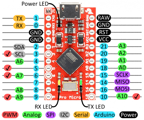
2. i plan to use a promicro because i'm cheap and haven't really soldered before. what's the max number row/columns i can use with it ?
3. would anyone be kind enough to take a quick look at the plate and let me know if there's any glaring mistakes ?
Here's the layout I'm looking for and attached is are the 3 output files.

Posted: 29 Jan 2015, 15:15
by Halvar
Pro micro:
https://www.sparkfun.com/products/12640
So 18 GPIOs, which means (#rows + #columns) <= 18
Teensy 2.0: 24
Teensy++ 2.0: 36
---
EDIT: 18
Posted: 29 Jan 2015, 15:18
by Nuum
You could add some keys to the top right corner, similar to the Leopold FC660M/FC660C, seems to be a wasted space to me.
Posted: 29 Jan 2015, 15:45
by gogusrl
I thought about that but then I'd have no room to put the teensy and I hate having keys on the right of Enter.
Guess I'll have to buy a teensy to cover it.
Posted: 05 Mar 2015, 21:41
by swill
gogusrl wrote: I think this is the best thread to ask for some help.
I finally decided to build my first hand-wired keyboard. After pulling my hair out with various cad software, I found swill's plate building tool (
http://builder.swillkb.com/ )
Now I have a few questions :
1. how to I convert the resulting stl/brp/stp to a 2d dwg / dxf / cdr for cnc/laser cutting (everything i've tried gives me a 3d mesh)
2. i plan to use a promicro because i'm cheap and haven't really soldered before. what's the max number row/columns i can use with it ?
3. would anyone be kind enough to take a quick look at the plate and let me know if there's any glaring mistakes ?
Here's the layout I'm looking for and attached is are the 3 output files.
I just saw this. My plate building tool (
builder.swillkb.com) has been updated since you last used it and it now supports the export of a DXF file. The DXF file format I am using is R12 though, so it does not include the units of measure (UOM). The plate is built in millimeters, so if you open it in a CAD program and you default UOM is inches, you will have to change the UOM to 'mm' and then resave it. I have added help text to on how to do this when you download the file. I have added a bunch of features recently including all the layers for a sandwich case. Maybe check it out again. Cheers and I am glad it was helpful.
Here are some screenshots for reference...

- The UI for building a CAD
- plate_builder.png (200.8 KiB) Viewed 9139 times

- The CAD results
- plate_builder_result.png (269.68 KiB) Viewed 9139 times
Posted: 05 Mar 2015, 21:47
by scottc
Really cool tool, thanks a lot for developing it! I've had no excuse to actually use it through to manufacturing yet, but I had a look at a DWG produced and it's great.
Posted: 07 Mar 2015, 10:41
by matt3o
too many screw holes
you need far less than that. but great tool anyway!
Posted: 09 Mar 2015, 14:48
by Ninhalem
This is an awesome tool! Any chance that you can update the application to support layouts like the ErgoDox or something similar to it? I'm working on a gamepad layout that is similar to the hand layout of the ErgoDox.
Posted: 17 Mar 2015, 23:05
by swill
Ninhalem wrote: This is an awesome tool! Any chance that you can update the application to support layouts like the ErgoDox or something similar to it? I'm working on a gamepad layout that is similar to the hand layout of the ErgoDox.
I already support the ergodox alphas, but I currently do not support rotated groups of keys. I have had lots of requests for that and it is on my roadmap, but I have not had a chance to add that support yet.
Posted: 17 Mar 2015, 23:07
by swill
matt3o wrote: too many screw holes
you need far less than that. but great tool anyway!
Haha... That is all configurable. For the sandwich case you need at least 4 and it supports any even number greater than 4.
Posted: 17 Mar 2015, 23:10
by swill
Not to pollute your thread, but I figured I would add a quick note since some people seem interested. I added support for the standard Poker case as well now, so you can cut replacement plates for your poker (or GH60 or whatever other 60% PCB you have). I will hopefully be able to get universal TKL and full sized cases up there soon too.
Posted: 17 Mar 2015, 23:38
by chzel
swill wrote: I added support for the standard Poker case as well now, so you can cut replacement plates for your poker (or GH60 or whatever other 60% PCB you have).
You couldn't have better timing! Thank you!
Posted: 12 Feb 2017, 16:01
by Sigmoid
So since it's just an idea so far I decided to resurrect this thread instead of opening a new one...
I'm thinking about the merits of going the pcb mount route vs. plate mount. There is plenty discussion on the merits of plate vs. pcb and vice versa from a user's perspective, it seems like an individual taste thing... It definitely seems simpler to reliably build a pcb mount one though. For one, no plate to cnc. Even if one cnc's a case, a lot less can go wrong with that than with a switch mount plate..
I'm wondering if anyone has used this approach in diy, and what might be the best approach for mounting / securing the pcb itself - just on the edges, or with some kind of support -, what's the "standard" pcb thickness for a keyboard...
Posted: 12 Feb 2017, 16:39
by Wodan
Actually I believe a PCB mount custom keboard is much more difficult to make. For one, you will need a PCB which you don't need when hand wiring a freaky plate mounted custom design. Then you will have to add mounting points to that PCB. There is a quasi-standard for 60% PCB monting points which is just pathetic so you might want to go your own route.
Then you need a plate to fix your pcb on - or a case to rest your pcb in. Either way this will be quite a task as a PCB isn't exactly a very even component and it has to sit perfectly in the case to give you a nice typing experience.
Posted: 12 Feb 2017, 17:11
by Sigmoid
Actually, getting a pcb is as easy (or easier) than getting a steel or aluminum plate cnc'd. There is a huge industry for prototyping pcbs, and prices have dropped through the floor. As for mounting points, the fab shop does drilling and cutting based on the CAM files you send them, so it's nothing you have to worry about (unless they mess up).
In the electronics maker community, using pcbs as front panels is kind of a trend - as you'll have to get a pcb fabbed anyway, and it's guaranteed by the fab shop to be accurate down to a mil (1/1000th of an inch)...
Yes, cases need to be considered.. I'm wondering if a layered case design with the board as one of the layers, and a solid backplate for solidity and protection would give enough stability.