Page 7 of 9
Re: Converting an IBM Pingmaster
Posted: 28 May 2017, 19:59
by gazza341
hasu wrote:I think without decent pullups the converter won't work in some severe situations, or it is just lucky that it appears to work
gazza341,
Don't pull-up resisters help? assming you have no pull-ups.
Hi Hasu,
Firstly, thank you so much for the time and work put in on the TMK editor and other related stuff - it's much appreciated.
As for the pull-up resistors - I haven't tried them yet, I was mainly comparing notes in an attempt to help Coffee with his intermittent character repetition issues.
Converting an IBM Pingmaster
Posted: 28 May 2017, 20:03
by gazza341
just_add_coffee wrote:
My soldering should always be doubted. I didn't take a pic this time, but it's a bit better than before and I'm slowly improving overall. Hopefully I'll get my act together before the Ergodox Infinity on Massdrop gets here
Haha, I've gone for that - no doubt we'll be abusing deskthority bandwidth when those arrive - it will be a show'n'tell fest! [FACE WITH STUCK-OUT TONGUE AND WINKING EYE]
Sent from my iPhone using Tapatalk
Posted: 29 May 2017, 21:36
by just_add_coffee
I will definitely give that a shot. Well that, and soldering better. I think the key for me will be figuring out how to put everything together such that it stays together before soldering.
And as Gazza said, thank you for the TMK! I plan to convert all of my IBM and Unicomp projects to TMK; I believe that defining layouts and macros graphically is the ideal way to go in making these old boards relevant again.
Posted: 29 May 2017, 21:42
by just_add_coffee
Wingklip wrote:
It might be safe to say that the controller itself has some issue with soldering or something. Did you make sure that the grounding wire was attached?
If you mean the green wire that screws into the base plate, it comes soldered to the wire mesh shielding inside of the original cable. When I've used part of the original cable, I did attach the grounding wire. The other times, no.
And, at this point, it seems like shielding didn't have any noticeable effect on remedying my issues.
Posted: 04 Jun 2017, 16:56
by just_add_coffee
Welp ... I had a friend come by Thursday with an oscilloscope, and the keyboard was on its best behavior ... couldn't find any problems while they were here. But Friday, it was screwing up again, even after putting in a brand new Teensy 2.0.
So yesterday I broke out a new Pingmaster, installed the Teensy and the 1kohm resisters, and this board has been operating perfectly since.
I'm glad to finally have this board operating well, and I'll experiment with trying to diagnose the old Pingmaster. Maybe there's a faulty solder (not mine) in there.
Posted: 06 Jun 2017, 16:13
by Wingklip
Good heavens! Thank God you found the cause of t problem, it's been running circles around us all for 2 months xd
Glad it's fixed man, pics of it didn't happen

Posted: 06 Jun 2017, 18:40
by just_add_coffee
Wingklip wrote: Good heavens! Thank God you found the cause of t problem, it's been running circles around us all for 2 months xd
Glad it's fixed man, pics of it didn't happen


Hole for flashing the Teensy.

Q U A L I T Y

I'm glad to finally have this board functional. Sometime in the future I'll play around with replacing the speaker with a diode and a vibration motor.
Posted: 06 Jun 2017, 19:20
by SaltyMcSushi
just_add_coffee wrote: I'm glad to finally have this board functional. Sometime in the future I'll play around with replacing the speaker with a diode and a vibration motor.
Super cool idea! Do you know of any keyboards that do that, or projects to do that? It would also be cool to be able to adjust the vibration with the wheel on the back of the keyboard. Variable tactility keyboard!
And congratulations! Personally, my wires snapped again and I didn't care to do everything over so I bought an external converter from Hasu. Works great. I'm going to mount it in a PCIe slot so I can plug my Pingmaster directly into my computer using the original connector. I'll provide pictures when the PCIe bracket arrives.
Posted: 10 Jul 2017, 16:49
by Wingklip
What hex file did you guys use for the pro micro? I've been trying the external active adapter firmware for the alps 4704 102 key chinese firmware but it does not seem to work at all.
Once only the buzzer was active and every time I typed I could hear it. Now that stopped altogether and the converter is still unable to output any text. i have the pinout correct, double checked that, but I don't think the firmware is working for some reason. PS: I used the keymap editor hex file and this is what I downloaded for the hex file
http://www.tmk-kbd.com/tmk_keyboard/edi ... 2Q7ICF74iA
Part No is 6113442, using the original cable and another DB9 female to Pro micro to convert the signal.
Posted: 10 Jul 2017, 18:35
by just_add_coffee
Hey Wingklip ... Is it possible that the Pro Micro is bad? Maybe it's worth switching out to see what happens?
Posted: 12 Jul 2017, 11:23
by Wingklip
Can I have whatever hex you uploaded pls?
Inb4 keyboard is bad D:
Posted: 12 Jul 2017, 13:22
by just_add_coffee
Wingklip wrote: Can I have whatever hex you uploaded pls?
Inb4 keyboard is bad D:
Here's a link to my layout.
Posted: 14 Jul 2017, 08:18
by Wingklip
Did it work without the 1 kOhm pull-up resistors but?
Posted: 14 Jul 2017, 09:31
by just_add_coffee
Wingklip wrote: Did it work without the 1 kOhm pull-up resistors but?
Yes, but not well. A key here or there would cease working, suddenly it would start rapid-firing keys that weren't pressed, and multiple presses would be needed to get output. I believe that one board was a lemon to begin with because putting my converter in another worked drastically better.
Posted: 14 Jul 2017, 11:15
by Wingklip
What would happen, say, if you had a 500Ohm resistor between the data and 5v line and the clock line?
Theoretically, that means you will have stronger voltage signal right? But would that also possibly mean frying the board?
Posted: 16 Jul 2017, 14:15
by just_add_coffee
Wingklip wrote: What would happen, say, if you had a 500Ohm resistor between the data and 5v line and the clock line?
Theoretically, that means you will have stronger voltage signal right? But would that also possibly mean frying the board?
On the Pingmaster I'm using now, I have a 1k ohm between VCC and Data and another between VCC and Clock. It definitely seemed to help, and these pullup resisters are recommended in the Soarer's Converter docs, which is where I got the idea from.
Posted: 17 Jul 2017, 02:48
by Mattr567
Posted: 18 Jul 2017, 19:45
by just_add_coffee

Poor Ten-Key. It gets no love.
Posted: 22 Jul 2017, 06:25
by Wingklip
WHAT AM I DOING WRONG

((((((((((((((
Triple checked the wiring, clock in the middle, ground on the left and data on the right.
WTF won't this work? I'm using Hasu's 4704 firmware rev 1 for the 102key 6113442 but it stil doesn't work or type at all. I can hear it turn on with the electrical slight noise in the buzzer but nothing after that.
Checked all the wiring but it seems it still goves me nothing :::::/

- IMG_20170722_141503_HDR.jpg (3.41 MiB) Viewed 7503 times
Posted: 22 Jul 2017, 07:23
by Wingklip
Jokes, I got it working now, beeper and all. I think I didn't flash the pro micro properly or it broke or something like that xd
Thanks for the help, guys! Been a pleasure.
Posted: 01 Aug 2017, 20:27
by just_add_coffee
Cool!!!
So how do you like typing on it?
Posted: 01 Aug 2017, 22:00
by Mattr567
Posted: 02 Aug 2017, 05:37
by Wingklip
just_add_coffee wrote: Cool!!!
So how do you like typing on it?
I find it quite nice, but it's profiling makes it a bit awkward to game on it.
Also I think I'm using your firmware right now so the keybinds are all off from my norm of the IBM model F XT, gotta fix that first xd
Posted: 02 Aug 2017, 17:06
by just_add_coffee
Wingklip wrote: just_add_coffee wrote: Cool!!!
So how do you like typing on it?
I find it quite nice, but it's profiling makes it a bit awkward to game on it.
Also I think I'm using your firmware right now so the keybinds are all off from my norm of the IBM model F XT, gotta fix that first xd
My keybinds are PERFECT. Any changes would make them LESS perfect. PERFECT > less perfect. That's just math.

To me, those switches are extremely sensitive, which is a double-edged sword. On other IBMs, I can lightly rest my fingers on the home row; do that on a Pingmaster, and you trigger the key. But aside from that, it's a blazing-fast typing board!
Posted: 04 Aug 2017, 06:21
by Wingklip
nah neck youself trashy layout xddddddd
Control as Caps is justice !!¡!!!¡
Posted: 05 Aug 2017, 17:51
by just_add_coffee
Wingklip wrote: nah neck youself trashy layout xddddddd
Control as Caps is justice !!¡!!!¡
Yeah, I oughta practice toggling the damned layers correctly. Why does change have to be so hard???
Posted: 03 Sep 2017, 18:22
by depletedvespene
OldIsNew wrote: 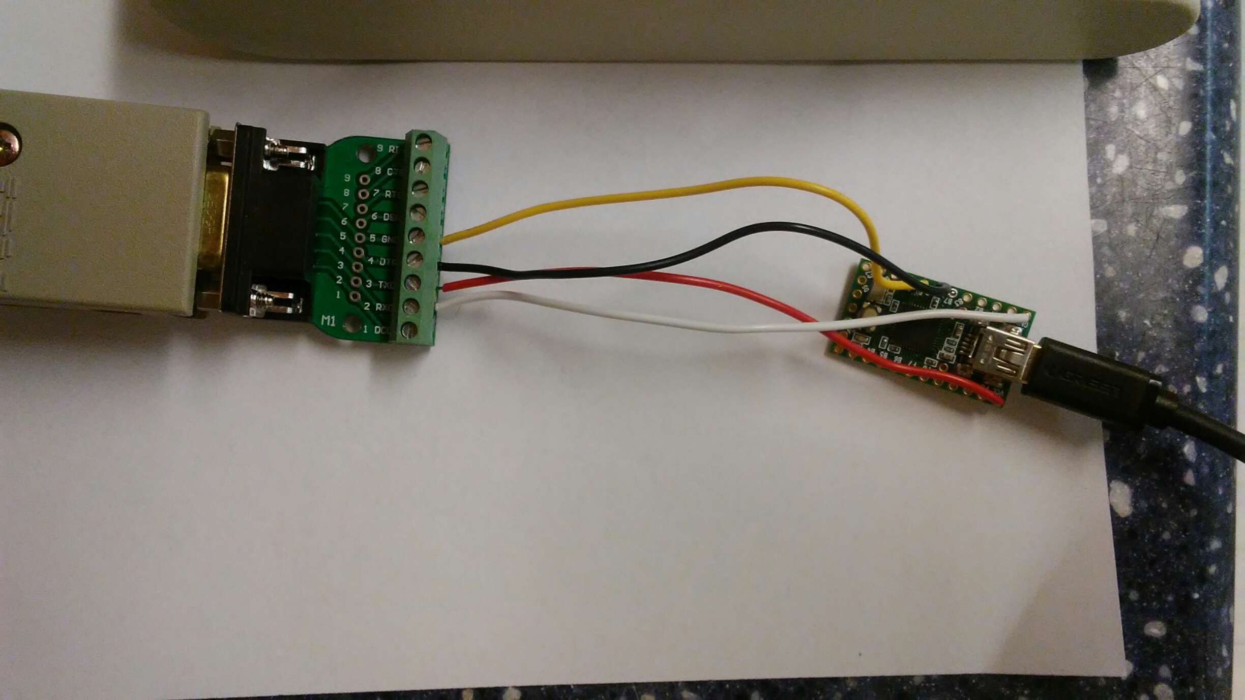
I'll start out by admitting that when it comes to hardware I am
useless; to make things worse, I seem to lack the basic knowledge that would let me gather the information I need just from reading threads like this one. I'm straight up confused and need a bit of baby guidance, so to speak (the programming aspect, on the other hand, isn't looking difficult and I'll probably get by nicely once I get to it).
I bought a few Pingmasters, and I want to actually use 'em; I do
not want to open them up (see above) or even cut their cord (see above), so I prefer to have an external solution, such as the one in the quoted picture, that would not modify the keeb itself in any way,
and I want to learn how to do it myself.
But... I don't fully understand what I am looking at in the picture. Please fill in the blanks and correct the mistakes I've made here:
- The keyboard's plug is plugged to a _________ (DB-9 adapter to ???), of which the green bit IS an integral part.
- The green bit connects to the wires with NO soldering required on this part.
- The four wires connect on their other ends to a
pro micro; they ARE soldered here.
I've seen "ProMicro", "pro micro", "pro micro controller", "teensy" and other terms used interchangeably. What is the exact name of this part? Searching for "promicro controller", I've found 5V and 3.3V models. Which one is this?
WHERE do I buy those?
Thanks.
Posted: 03 Sep 2017, 18:54
by OldIsNew
I used a DB-9 breakout board from Amazon, can solder to it, but I used the screw terminals (no soldering) and they seem to work fine.
https://www.amazon.com/gp/product/B00WW ... UTF8&psc=1
The microcontroller board I used is a Teensy 2.0, which can also get from Amazon (or PJRC directly), and yes the wires are soldered to the Teensy (the Teensy 2.0 is 5V). :
https://www.amazon.com/gp/product/B00NC ... UTF8&psc=1
This is some wiring info from TMK documentaton:
------------------------------------------------------------------------------------------------------------------------
Keyboard Plug from front:
DSUB-9
-------------
\ N 2 3 4 5 /
\ N N N N /
---------
2 GND
3 VCC 5V
4 DATA
5 CLOCK
N No connection/No pin.
Connection
In case of using ATMega32U4/U2 (EDIT: The Teensy 2.0 uses the ATMega32U4)
1. Supply power with VCC and GND.
2. Connect CLOCK to PD1 and DATA to PD0. You can change pin with config.h.
3. Optionally you may need pull-up resistor. 1KOhm probably work.
-----------------------------------------------------------------------------------------------------------------------
A couple helpful links, github for the firmware hex file to load on the Teensy and tmk-kbd has firmware file and editor for the keyboard layout:
https://github.com/tmk/tmk_keyboard/tre ... usb/binary
http://www.tmk-kbd.com/tmk_keyboard/edi ... 4_usb_alps
Posted: 03 Sep 2017, 19:28
by depletedvespene
Thank you, OldIsNew!
One more question:
OldIsNew wrote: 3. Optionally you may need pull-up resistor. 1KOhm probably work.
Why would I need a pull-up resistor? (and where would it go?)
Posted: 03 Sep 2017, 20:02
by OldIsNew
depletedvespene wrote: Thank you, OldIsNew!
One more question:
OldIsNew wrote: 3. Optionally you may need pull-up resistor. 1KOhm probably work.
Why would I need a pull-up resistor? (and where would it go?)
That is from Hasu's documentation (
https://github.com/tmk/tmk_keyboard/tre ... bm4704_usb ) so I left it in, but mine worked fine without the addition of a pull-up resistor so I never looked any further into it, not sure if he was referring to both the DATA and CLOCK lines - it's a good question - does anyone know for sure?

