I have done bits of programing for a few years now, just when I need to. But since I started reading about Soarers, hasu and HaaTa's coverters/controllers I became instrested in electronics so I went out and bought an arduino.
I've got through the first 3 tutorials here http://www.ladyada.net/learn/arduino/index.html Didn't find them too hard. Lets see how long it takes for my brain to boil.
After doing these tutorials any idea where to look to take it further? This is the kit I bought http://www.ebay.co.uk/itm/120948959521? ... 1497.l2649
Arduino talk
- fossala
- Elite +1
- Location: UK
- Main keyboard: HHKB Type-S
- Main mouse: Rollermouse Free2
- Favorite switch: Topre
- DT Pro Member: -
Can anyone point me to a good tutorial about breadboards. I'm wiring my arduino to them for projects and I'm understanding the code part but I can't get my head around why I'm putting the wires in the breadboard in certian places.
- RC-1140
- Location: Germany
- Main keyboard: Unicomp Terminal Emulator
- Main mouse: Razer Mamba
- Favorite switch: Buckling Spring
- DT Pro Member: -
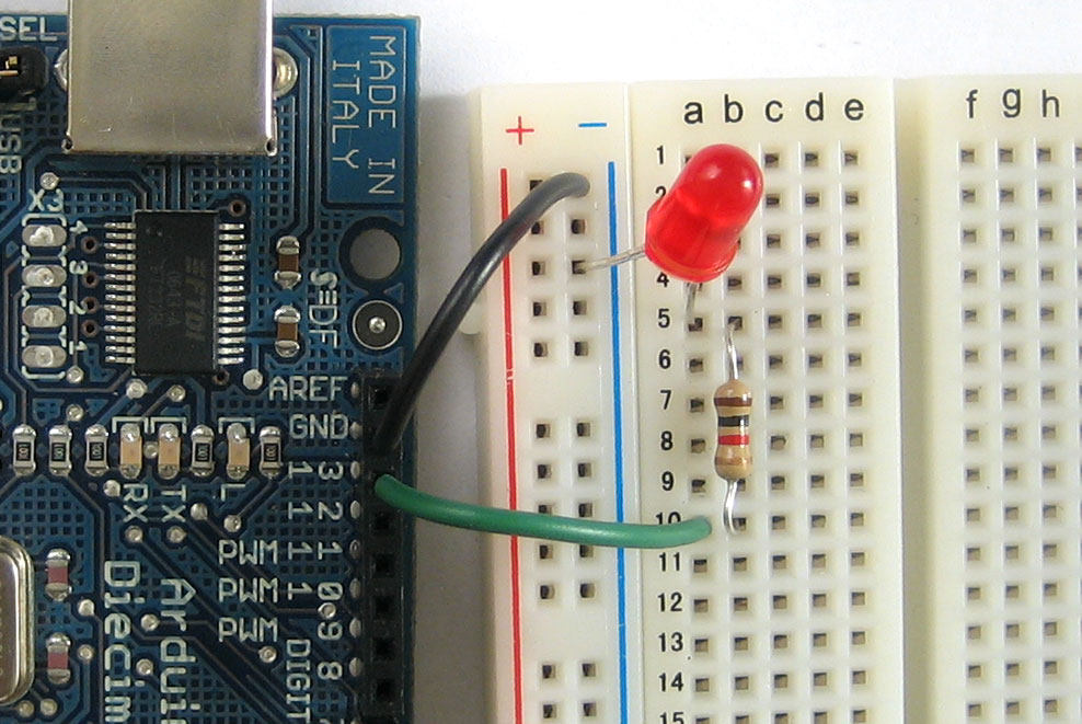
what do you need to know? Usually the connectors of a breadboard are connected horizontally, with maybe two lines of pins connected vertically. So you place VCC and GND on the two vertical ones, place the Arduino in the breadboard, and can access the pins of the Arduino on the connectors next to the Arduino pins.
- RC-1140
- Location: Germany
- Main keyboard: Unicomp Terminal Emulator
- Main mouse: Razer Mamba
- Favorite switch: Buckling Spring
- DT Pro Member: -
as I said, the + (VCC) and the - (GND) lines are connected vertically. The lines 1,2,3 and so on are connected horizontally. So 1a-1e are connected, 2a-2e are connected and so on.
You connected the GND Pin of the Arduino to the GND line of the breadboard. Then you connected the LED no the line 5. Also connected tho the line 5 is the resistor, which is connected to the line 10. Line 10 is then connected to the output pin of the Arduino.
You connected the GND Pin of the Arduino to the GND line of the breadboard. Then you connected the LED no the line 5. Also connected tho the line 5 is the resistor, which is connected to the line 10. Line 10 is then connected to the output pin of the Arduino.
