Hello!
To be completely honest, I don't have a convincing reason as to why I'm trying to design a new switch... and I'm not gonna try to come up with one, because this project actually started from me losing a lot of sleep nights after nights as I couldn't stop thinking about this switch idea, and I know myself well enough to realize that I need to do something about it before I turn insomniac

But I can tell you why I think this design is interesting, and I'll let you guys decide if it could be beneficial to the community!
 DISCLAIMER:
 I'm not a professional designer by any standard, I'm just a game programmer who knows a little bit of Sketchups (pretty useful for making placeholders). So, please don't expect professional quality CAD files from me

However, I did quite a few 3d printing to verify that the general design will
'most likely' work (definitely didn't work the first couple of time, this is actually ver.
11 
)
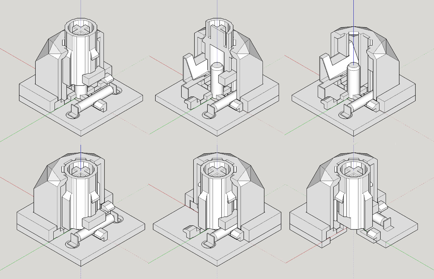
First let's look at what it looks like:
- switch-iso.jpg (120.17 KiB) Viewed 7454 times
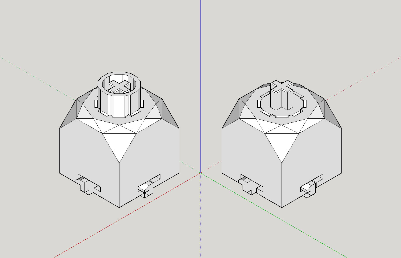
This image shows how it looks in general and 2 slider variations. I'm not sure which one will feel better or smoother, but I know that artisans with THICC stem will not fit the walled version, and the walled version may provide extra stability with SA caps. The main housing is 14mm x 14mm x 14mm and the total travel is 4mm. It is designed from to ground up
for enthusiasts, meaning, I'm not trying to design the 'best' switch in any category in particular, but I want it to feel great, easy to customize and create variations, a joy to work with, and allows for simple and high quality keyboard designs. It is not MX compatible except for the keycap mount and spring. I tried making it completely MX compatible at first, but in the end it greatly limits what I originally wanted to create, and I don't even know if this thing will go anywhere more than a few 3d printed fidget toys sitting on my desk, so why not try going all-out crazy first

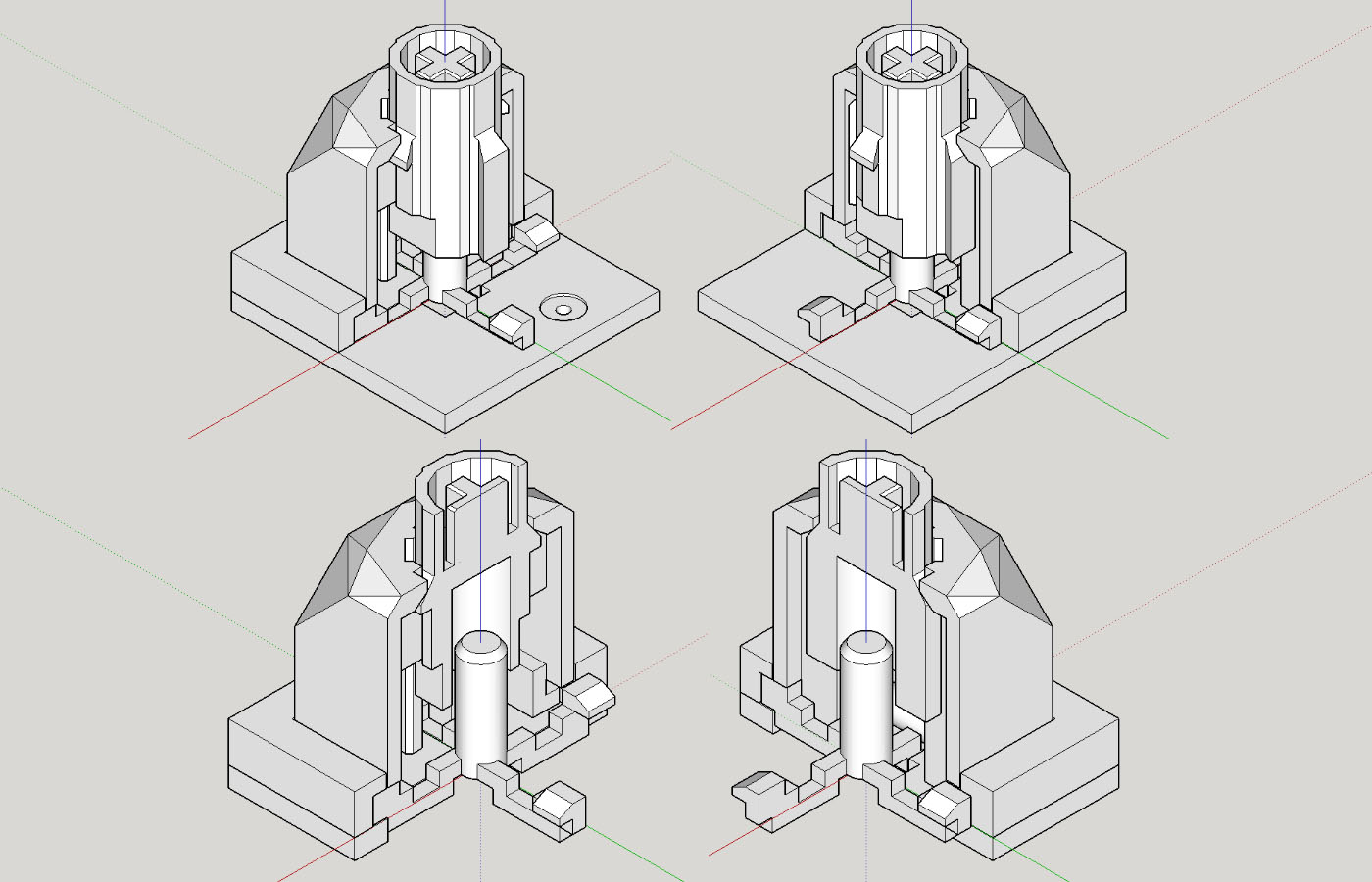
Here is the exploded view:

- switch-iso-explode.jpg (151.37 KiB) Viewed 7454 times
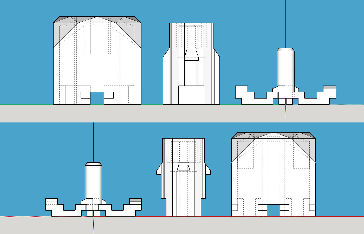
- switch-front-back.jpg (148.54 KiB) Viewed 7454 times

- switch-top-bottom.jpg (141.58 KiB) Viewed 7454 times
The spring and contact are not shown here, just the slider and housing. I've designed it so that any MX spring will fit, and you can probably see where the spring will be, so I didn't bother drawing it. As for the contact, there are plenty of space in the housing, so there are many options, we'll get to that later.
At this point you might be wondering about the cross-shaped piece that hold the spring. There are reasons why it look like that: First, it allows for an easy way to open and close the switch without any tools while still securely holds everything in by clipping to the main housing with the notches on all 4 sides. Second, the cross act as mounting, holding the switch to the pcb without any tilt. Third, dust can be blown out of the switch without disassembly. And finally, light can shine through the switch directly from bottom-center (we'll see where to put the LED in a bit).
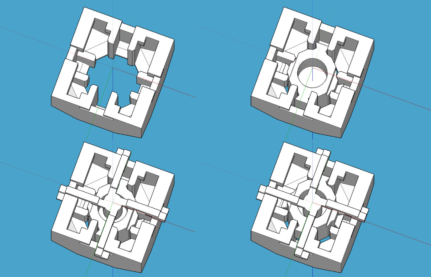
This view from the bottom gives a better view of how the housing, slider and the cross fits together and a better view of how the slider is held inside the housing:
- switch-iso-bottom.jpg (178.31 KiB) Viewed 7454 times
Here you can see the grooves on all 4 sides that are keeping the slider as vertical as possible while sliding. You can see 2 of the 4 grooves extends all the way down to the bottom. The longer grooves are what mainly keep the slider on its axis, pretty common stuff, many switch have something like this. The shorter grooves are there meant to provide additional stability while still give enough room to add the mechanism for contact and tactility.
Here is how the switches are installed on the pcb and how they are held in place:

- switch_pcb_plate_explode.jpg (324.01 KiB) Viewed 7454 times
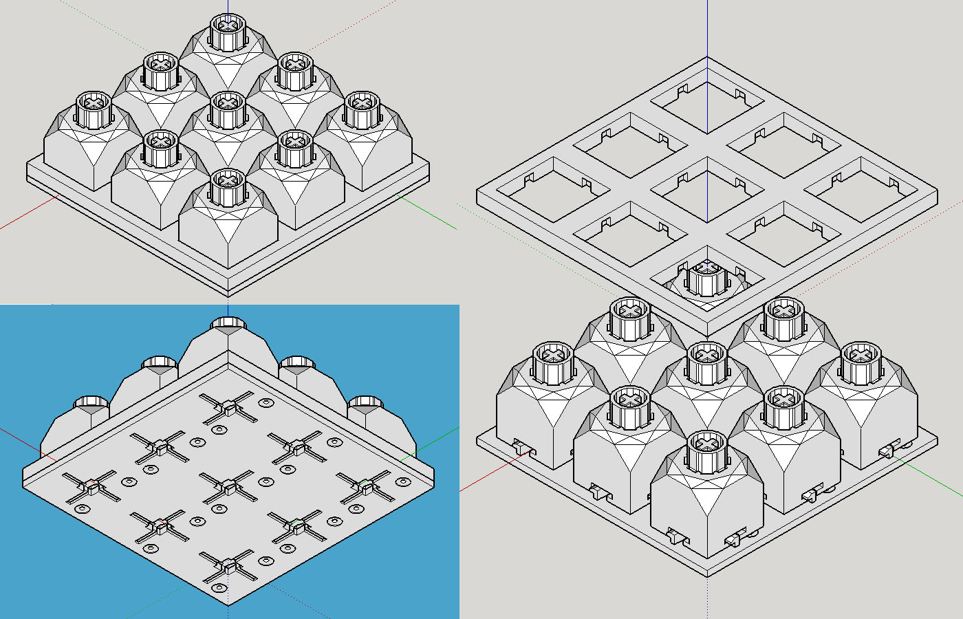
- switch_pcb_plate.jpg (302.75 KiB) Viewed 7454 times
- switch-xsection.jpg (170.14 KiB) Viewed 7454 times
The bottom rectangle that the switch sits on is the pcb, here you can see how the cross piece mount onto the pcb and how it can keep the switch from tilting. The top rectangle is what I call the
'retainer'. It is meant to sandwich with the pcb by screws and keep the switches in place by holding on to the notches on all 4 sides of each switch. The retainer is not meant to be the 'plate' or part of the case, it should be inside the case and made of non-conductive material. Solder is not needed as the switch should make a firm contact to the pcb from the sandwiching of the retainer and the pcb.
If this design works out, assembling switches to the pcb will be very simple, add switches, screw in the retainer, done.
Here you can also see the how the holes on the pcb can allow LED to be placed on the bottom side of the PCB, and still shine through the bottom-center of the switch, allowing the same LED to be used for both under-glow and switch backlit. You can even use separate led strips for each row instead of soldering all LEDs to the pcb.
Now let's talk contact, here is where I get a little crazy... But first, let me say that I intentionally design the switch so that it has
plenty of room for contact mechanism, not nailing down
the contact for this switch. But because the contact is kind of important for a switch, and a switch is not a switch without the contact, so I still want to give my idea of the contact that I would like to see the most
- switch-xsection-contact.jpg (218.71 KiB) Viewed 7454 times
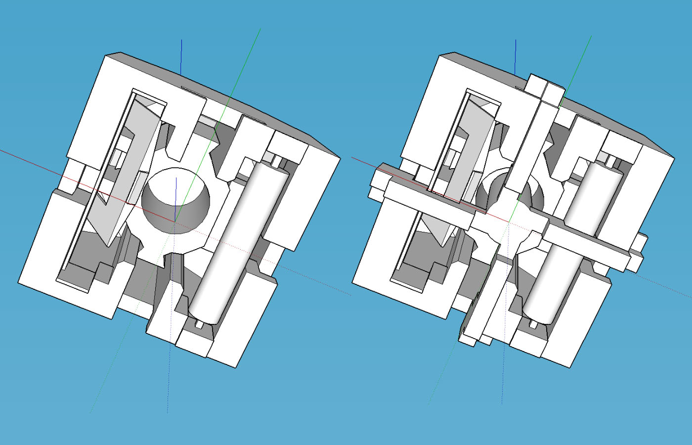
- switch-contact-bottom.jpg (180.22 KiB) Viewed 7454 times
Sorry, it is kinda hard to find an angle that can explain it visually. But for those who can make out what it is... Yes! It is a reed switch! The tube in the picture is a reed switch, the rectangle block above it is a magnet, and on the opposite side is a click-leaf similar the ones in the beloved Alps switches. The size of the reed switch tube is 10mm, although not the most commonly available types, I was able to find several suppliers through a quick search, so at least it's out there. If the reed switch idea turns out to be a bad idea due to cost, availability, or other reasons, the space could fit anything from: a magnet for hall-effect switch, an Alps-style switch plate, an optical switch sensor, etc.
And that's it for now! Thank you for your time going through the long post, I'm always looking for feedback to improve on this design so feel free to let me know how stupid I am

And finally here's a GitHub link to the source file for the switch for those who want to take a closer look at the 3d file:
https://github.com/mustcode/switch
edit: fixed some typos


