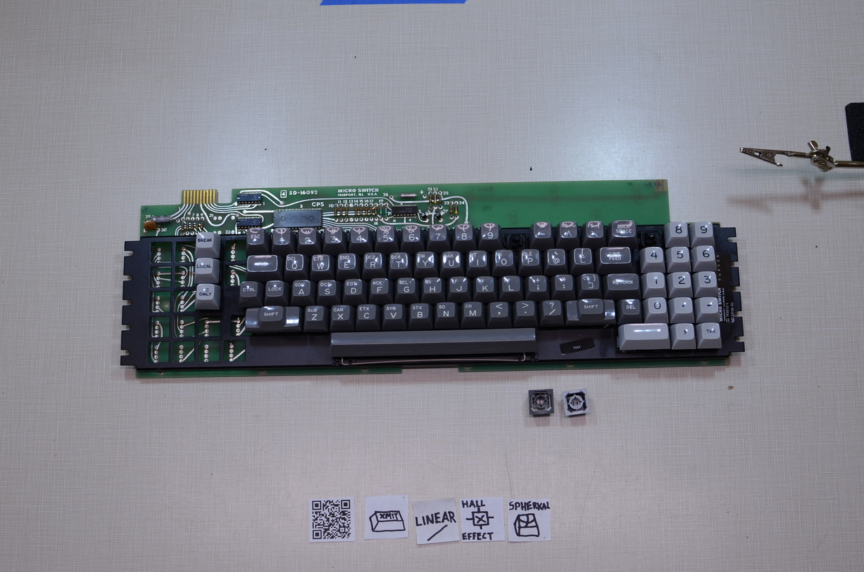
There are some tricks for possible NKRO support that I'll get to later but I think all of them will require a new PCB. I'm working on a 1KRO solution that is an easy enough retrofit for anyone with one of these boards today, and may or may not get to designing a new PCB.
I've been playing with EAGLE some. Here is a schematic for a 2x2 matrix of these Hall switches. This small example is exactly how the switches on the board are wired (though the resistor value may be off; that doesn't matter). There is one pull up resistor per row and one pull up resistor per column. When a switch is pressed, it pulls its row and its column, from high to low, for 60µs ± 3µs. The precision here is pretty good.
Now consider what happens if A (upper left - row 1, column 1) and D (lower right - row 2, column 2) are pressed at exactly the same time. For 60µs, all of row 1, row 2, column 1, and column 2 are low. There is absolutely no way to determine if the user has pressed AD, BC, ABC, ACD, BCD, ABD, or ABCD. Since there is no way to tell the only sensible thing for the keyboard firmware to do is to toss away the result and act as if no key was pressed. This is easy to detect by AND'ing together the results of all the column scans for which a row was pressed, and blocking if the result AND's to something other than zero.
In pseudocode this might look like:
Code: Select all
#define NUM_ROWS 6
/* Holds results of one pass of matrix scan. Use high bit to note that row was set. */
uint32_t sense[NUM_ROWS];
uint32_t block;
uint8_t i, row;

/* Main scanning loop. */
while(1) {
for(i=0; i<NUM_ROWS; i++)
{
    block = 0;
    /* Reads row i of sense matrix. Lower bits are set if columns are set. High bit is set if row is set. */
    sense[i] = read_row(i);
    block &= sense[i];
}
if(block) break;
/* Continue keyboard sensing. */
}
Of course this only blocks when two switches are pressed together (or in an overlapping fashion that triggers the blocking logic). With a 60µs pulse width the chances of this happening are vanishingly small - perhaps this is why the Micro USA engineers chose this width. But the chance must not be dismissed.
Now, back to those aforementioned tricks. There are two that come to mind:
1. Use the output of a Hall sensor to drive the gate of a FET. Then, use the FET itself as a regular old switch with a diode across it, and scan this as if it were an array of mechanical switches. This would give NKRO.
2. Wire every Hall switch to its own pull up resistor and select between these through one or more multiplexers. Then I'm able to detect individual switches. The existing board sort of does this but is still limited to 1KRO because of the shared row and column sense lines.
Both of these techniques work with "hold low" and "pulse low" switches. In the case of the former you'd have true NKRO since you know when presses are pressed and released. For the latter, you still only get press events from the hardware but at least you can detect the presses without blocking.
A while ago HaaTa proposed a solution involving strobing the power lines to achieve NKRO. I worry about this proposal. For one, I don't know how the Hall hardware would respond to being driven with a 33kHz square wave. For two, I don't know how these switches are calibrated - either with a fixed factory calibration or a dynamic power on calibration. It's possible that rapid power cycling would throw off the calibration. Three, I don't know what sort of delay the switch gives between power on and being able to sense; we may not be able to strobe power fast enough.
Fun times.

